Electrolux E48DF76EPS Installation Instructions - Page 32
STEP 8, Perform Pressure Tests, STEP 9, Adjust Air Shutter Gaps
 |
View all Electrolux E48DF76EPS manuals
Add to My Manuals
Save this manual to your list of manuals |
Page 32 highlights
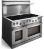
STEP 8 Perform Pressure Tests 8-1 Connect the U-tube manometer to the LPG supply line. 8-5 Make sure all knobs on the front of the range are in the off position. 8-2 With electrical power to the range disconnected, 8-6 Connect the U-tube manometer to the left rear open the LPG supply valve. burner's main orifice with 3/8" surgical tubing. 8-3 Verify that the pressure is above 11 inches water 8-7 Open the LPG supply valve. Turn on the left rear column (WC) and below ½ PSI. Consult the burner. The manometer should read 10 inches factory if the pressure is not within the above WC +/- ½ inch. Contact the factory if the limits. pressure does not meet specifications. 8-4 Close the LPG supply valve. Connect the range to the LPG supply line. 8-8 Turn off the burner and the gas supply valve. Place end of tube over main orifice Figure 8-1 Pressure Test Set-up STEP 9 Adjust Air Shutter Gaps 9-1 Determine the appropriate air shutter part number for the left rear burner from Table 9-1 on page 9. Be sure to match the model number and burner location. The shutter part number appears on its side. 9-2 Thread the air shutter onto the left rear shutter connector about 6 turns (see Figure 9-1). 9-3 Reinstall the burner base (see Figure 9-1). 9-4 Measure the gap between the end of the shutter connector and the opposite end of the shutter opening with the pocket rule (see Figure 9-2). 9-5 Compare the measured gap to the gap listed in Table 9-2 for the appropriate model number and the burner location. 9-6 Hold the shutter connector with the 8" adjustable wrench. Adjust the air shutter using the 6" adjustable wrench until the gap is to within 1/16" (1.6 mm) of the gap indicated in the table. 9-7 Secure the shutter with thread-locker. 9-8 Repeat steps 9-1 through 9-7 for the remaining burners. 9-9 Check to make sure that the compression nut is tightened into the back of each shutter connector. Page 8
-
 1
1 -
2
-
3
-
4
-
5
-
6
-
7
-
8
-
9
-
10
-
11
-
12
-
13
-
14
-
15
-
16
-
17
-
18
-
19
-
20
-
21
-
22
-
23
-
24
-
25
-
26
-
 27
27 -
 28
28 -
 29
29 -
 30
30 -
 31
31 -
 32
32 -
 33
33 -
 34
34 -
 35
35 -
 36
36
 |
 |
