Epson DM-D210 User Manual - Page 6
When using the USB cable of DM-D110/DM-D210, Changing the Orientation of the Display Unit - driver
 |
View all Epson DM-D210 manuals
Add to My Manuals
Save this manual to your list of manuals |
Page 6 highlights
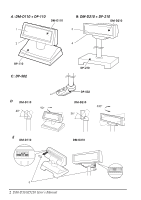
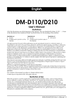
When using the USB cable of DM-D110/DM-D210 ❏ Do not connect to a USB connector of TM printer or USB hub which has limited power supply capacity. Doing so will exceed the power supply capacity and cause the TM printer or USB hub to break down. ❏ USB RS-232 Convert Driver (DM-D110(USB)_VCPdriver_Ver.2.xx.zip) is required to use DM-D110/DM-D210. The driver is not included with DMD110/DM-D210. Download it from the following URL, and install it before use. See "Downloading Drivers, Utilities, and Manuals" on page 5. After installing the above driver, the computer will recognize DM-D110/DMD210 as a USB device and add a virtual COM port. This product will be recognized as a serial device and can be used via a COM port. Note: If you use a TM-i series or TM-DT series printer, you do not need to install USB RS-232 Convert Driver. Changing the Orientation of the Display Unit The angle and direction of the display unit can be changed by holding the struts with your hand while moving the display unit. The display unit will move with only light pressure, so do not apply more pressure once the unit stops moving. Applying excess force to move the display unit may cause damage. When installed in the TM printer, there may be situations where the display unit cannot be turned to the desired direction. In these situations, remove the customer display and base unit, then adjust the position of the lug in the base unit before reattaching. See Illustration D. DIP Switches The DIP switches configure the communication settings and whether a self-test is required. See Illustration E. CAUTION: Do not remove the DIP switch cover until after turning the power off. Removing the cover while the power is turned on may damage the device. Remove the cables from the computer and remove the cover of the dip switch. If the cables are still connected to the computer during operation, this product may break down. 6 DM-D110/D210 User's Manual
-
 1
1 -
 2
2 -
 3
3 -
 4
4 -
 5
5 -
 6
6 -
 7
7 -
 8
8 -
 9
9 -
 10
10 -
 11
11 -
 12
12 -
13
-
14
-
15
-
16
-
17
-
18
-
19
-
20
-
21
-
22
-
23
-
24
-
25
-
26
-
27
-
28
-
29
-
30
-
31
-
32
-
33
-
34
-
35
-
36
-
37
-
38
-
39
-
40
-
41
-
42
-
43
-
44
-
45
-
46
-
47
-
48
-
49
-
50
-
51
-
52
-
53
-
54
-
55
-
56
-
57
-
58
-
59
-
60
-
61
-
62
-
63
-
64
-
65
-
66
-
67
-
68
-
69
-
70
-
71
-
72
-
73
-
74
-
75
-
76
-
77
-
78
-
79
-
80
-
81
-
82
-
83
-
84
-
85
-
86
-
87
-
88
-
89
-
90
-
91
-
92
-
93
-
94
-
95
-
96
-
97
-
98
-
99
-
100
-
101
 |
 |
