Fisher and Paykel OB24SDPX3 OB24SDPX Model Installation and User Guide (Englis - Page 22
Removing The Oven Door, Oven Shelf Installation And Removal, Replacing The Oven Light
 |
View all Fisher and Paykel OB24SDPX3 manuals
Add to My Manuals
Save this manual to your list of manuals |
Page 22 highlights
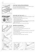
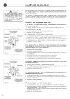
d4 Safety catch OVEN SHELF INSTALLATION AND REMOVAL The oven shelves are provided with a security block to prevent accidental extraction. They must be inserted operating as per figure 4.1. To pull them out remove shelf in the inverse order. Pay attention how to insert the shelves correctly (see figure 4.1). Fig. 4.1 B A Fig. 4.2 REPLACING THE OVEN LIGHT (fig. 4.2) Before any maintenance is started involving electrical parts of the appliance, it must be disconnected from the power supply. - Let the oven cavity and the heating elements cool down; - Switch off the electrical supply; - Remove the protective cover (fig. 4.2); - Unscrew and replace the bulb with a new one suitable for high temperatures (300°C) having the following specifications: 120V, 60 Hz, 25W, E14 - Refit the protective cover NOTE: Oven bulb replacement is not covered by your warranty. Fig. 4.3 REMOVING THE OVEN DOOR The oven door can easily be removed as follows: - Open the door to the full extent (fig. 4.3a). - Open the lever "A" completely on the left and right hinges (fig. 4.3b). - Hold the door as shown in fig. 4.3. - Gently close the door (fig. 4.3c) until left and right hinge levers "A" are hooked to part "B" of the door (fig. 4.3b) - Withdraw the hinge hooks from their location following arrow "C" (fig. 4.3d). - Rest the door on a soft surface. - To replace the door, repeat the above steps in reverse order. Fig. 4.3a A B Fig. 4.3b 22 C Fig. 4.3d Fig. 4.3c
-
 1
1 -
2
-
3
-
4
-
5
-
6
-
7
-
8
-
9
-
10
-
11
-
12
-
13
-
14
-
15
-
16
-
 17
17 -
 18
18 -
 19
19 -
 20
20 -
 21
21 -
 22
22 -
 23
23 -
 24
24 -
 25
25 -
 26
26 -
 27
27 -
28
-
29
-
30
-
31
-
32
-
33
-
34
-
35
-
36
-
37
-
38
-
39
-
40
-
41
-
42
-
43
-
44
-
45
-
46
-
47
-
48
-
49
-
50
-
51
-
52
-
53
-
54
-
55
-
56
 |
 |
