Fisher and Paykel OB24SDPX3 OB24SDPX Model Installation and User Guide (Englis - Page 24
installation to the cabinet
 |
View all Fisher and Paykel OB24SDPX3 manuals
Add to My Manuals
Save this manual to your list of manuals |
Page 24 highlights
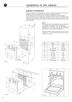
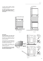
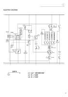
55 A Fig. 5.1 installation to the cabinet GENERAL INFORMATION The oven can be fitted in standard units, minimum width and depth 23" 5/8 (600 mm). Installation requires a compartment as illustrated in figures 5.1 and 5.2. On the lover side, the oven must lay on supports withstanding the oven weight. The oven should then be secured by 4 screws fitted into the holes provided at the sides of the oven (Fig. 5.3). If you open the oven door, you will see some screw holes. Remember the housing should not be free standing but be secured to the wall and/or adjacent fittings. NOTE H It is essential that when installing your oven, adequate air circulation is available within the installation. Inadequate air circulation may greatly impair the performance of your oven and may affect adjacent cabinets due to an increase in temperature. Adjust the hinges of cabinet door adjacent to the oven to allow a 5 - 7 mm gap between the furniture door and the oven frame. F C D E Ref. inches A 24" B 24" C 21" 7/8 max D 22" 3/64 max E 15/16" F 22" 3/64 G 23" 1/32 H 1" 31/32 I 23" 17/64 L 22" 7/16 min mm 609.5 608.7 556 max 560 max 24 560 585 50 591 570 min B B I G F C L A Fig. 5.2 24 D E Fig. 5.3
-
 1
1 -
2
-
3
-
4
-
5
-
6
-
7
-
8
-
9
-
10
-
11
-
12
-
13
-
14
-
15
-
16
-
17
-
18
-
 19
19 -
 20
20 -
 21
21 -
 22
22 -
 23
23 -
 24
24 -
 25
25 -
 26
26 -
 27
27 -
 28
28 -
 29
29 -
30
-
31
-
32
-
33
-
34
-
35
-
36
-
37
-
38
-
39
-
40
-
41
-
42
-
43
-
44
-
45
-
46
-
47
-
48
-
49
-
50
-
51
-
52
-
53
-
54
-
55
-
56
 |
 |
