Fluke 123 FE 123 & 124 Users Manual - Page 46
Using the 10:1 Probe for High Frequency, Measurements., Probe Attenuation.
 |
View all Fluke 123 manuals
Add to My Manuals
Save this manual to your list of manuals |
Page 46 highlights
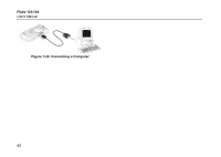
Fluke 123/124 Users Manual The reading now shows the risetime from 10%-90% of the trace amplitude and the voltage at the cursors in relation to the zero icon (-). See Figure 1-21. ~ Turn off the cursors. 38 Using the 10:1 Probe for High Frequency Measurements. Fluke 124 is supplied with a model VP40 10:1 Probe. Use of this Probe is recommended when you measure high frequency signals in circuits with a high impedance. The loading of the circuit by a 10:1 Probe is much lower than that of a 1:1 Shielded Test Lead. The following aspects must be observed when using a 10:1 Probe: Probe Attenuation. The Probe attenuates the signal 10 times. Proceed as follows to adapt the Test Tool's voltage readout to this attenuation. The example below is for a Probe connected to input B: Open the Scope menu. Open the Probes menu. Select PROBE on B ... Press ENTER Select 10:1 V
-
 1
1 -
2
-
3
-
4
-
5
-
6
-
7
-
8
-
9
-
10
-
11
-
12
-
13
-
14
-
15
-
16
-
17
-
18
-
19
-
20
-
21
-
22
-
23
-
24
-
25
-
26
-
27
-
28
-
29
-
30
-
31
-
32
-
33
-
34
-
35
-
36
-
37
-
38
-
39
-
40
-
 41
41 -
 42
42 -
 43
43 -
 44
44 -
 45
45 -
 46
46 -
 47
47 -
 48
48 -
 49
49 -
 50
50 -
 51
51 -
52
-
53
-
54
-
55
-
56
-
57
-
58
-
59
-
60
-
61
-
62
-
63
-
64
-
65
-
66
-
67
-
68
-
69
-
70
-
71
-
72
-
73
-
74
-
75
-
76
-
77
-
78
-
79
-
80
-
81
-
82
-
83
-
84
-
85
-
86
 |
 |