Fluke 1503 FE 1503-1507 Users Manual - Page 17
Input Terminals, Power-Up Options, Input Terminals, Table 6. Input Terminal Descriptions
 |
View all Fluke 1503 manuals
Add to My Manuals
Save this manual to your list of manuals |
Page 17 highlights
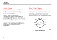
Input Terminals Input terminals are shown in Figure 4 and described in Table 6. 1 3 2 Figure 4. Input Terminals bbw08f.eps Insulation Testers Input Terminals . Item Table 6. Input Terminal Descriptions Description A Input terminal for resistance measurement. B Common (return) terminal for all measurements. C Input terminal for volts or insulation test. Power-Up Options Holding a button down while turning the Tester on activates a power-up option. Power-up options allow you to use additional features and functions of the Tester. To select a power-up option, hold down the appropriate button indicated while turning the Tester from OFF to any switch position. Power-up options are cancelled when the Tester is turned OFF. Power-up options are described in Table 7. 9
-
 1
1 -
2
-
3
-
4
-
5
-
6
-
7
-
8
-
9
-
10
-
11
-
 12
12 -
 13
13 -
 14
14 -
 15
15 -
 16
16 -
 17
17 -
 18
18 -
 19
19 -
 20
20 -
 21
21 -
 22
22 -
23
-
24
-
25
-
26
-
27
-
28
-
29
-
30
-
31
-
32
-
33
-
34
-
35
-
36
-
37
-
38
 |
 |
