Fluke 1503 FE 1503-1507 Users Manual - Page 19
Measuring Volts, Measuring Earth-Bond Resistance, Measuring Volts
 |
View all Fluke 1503 manuals
Add to My Manuals
Save this manual to your list of manuals |
Page 19 highlights
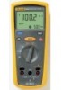
Measuring Volts 1507 INSULATION TESTER Figure 5. Measuring Volts bbw09f.eps Insulation Testers Making Measurements Measuring Earth-Bond Resistance Resistance tests should only be performed on de-energized circuits. Check the fuse before testing. See Testing the Fuse later in this manual. Connecting to an energized circuit while the test is active will blow the fuse. Note Measurements can be adversely affected by impedances of additional operating circuits connected in parallel or by transient currents. To measure resistance: 1. Insert test probes in the Ω and COM input terminals. 2. Turn the rotary switch to the O position. 3. Short the ends of the probes together, press the blue button and wait until dashes appear on the display. The Tester measures the probe resistance, stores the reading in memory, and subtracts it from readings. The probe resistance reading is saved even when the Tester is turned off. If the probe resistance is >2 Ω, the resistance will not be saved. 4. Connect the probes to the circuit to be measured. The Tester automatically detects if the circuit is energized. 11
-
 1
1 -
2
-
3
-
4
-
5
-
6
-
7
-
8
-
9
-
10
-
11
-
12
-
13
-
 14
14 -
 15
15 -
 16
16 -
 17
17 -
 18
18 -
 19
19 -
 20
20 -
 21
21 -
 22
22 -
 23
23 -
 24
24 -
25
-
26
-
27
-
28
-
29
-
30
-
31
-
32
-
33
-
34
-
35
-
36
-
37
-
38
 |
 |
