Fluke 744 Fluke 744 Users Manual - Page 40
Testing Continuity, Measuring Pressure, to select - accessories
 |
View all Fluke 744 manuals
Add to My Manuals
Save this manual to your list of manuals |
Page 40 highlights
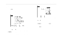
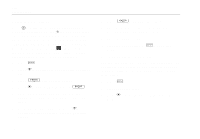
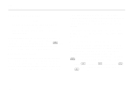
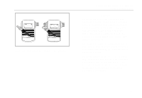
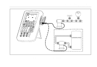
744 Users Manual Note When measuring frequency, you are prompted to select a frequency range. If you expect the frequency you are measuring to be below 20 Hz, press d to select the lower frequency range, then press e. 2. Connect the test leads as shown in Figure 10, depending on the measurement function. Testing Continuity When testing continuity, the beeper sounds and the word Short appears on the display when the resistance between the Ω MEAS jack and its common jack is less than 25 Ω. The word Open appears when the resistance is greater than 400 Ω. Proceed as follows to test continuity: 1. Remove power from the circuit to be tested. 2. If necessary, press M for MEASURE mode. 3. Press q twice so that Open appears. 4. Connect the calibrator to the circuit to be tested as Figure 10 shows. 30 Measuring Pressure Many ranges and types of pressure modules are available from Fluke. See "Accessories" near the back of this manual. Before you use a pressure module, read its Instruction Sheet. The modules vary in how you use them, how you zero them, what types of process pressure media are allowed, and accuracy specification. Figure 11 shows gage and differential modules. Differential modules also work in gage mode by leaving the low fitting open to atmosphere. To measure pressure, attach the appropriate pressure module for the process pressure to be tested as described in the module's Instruction Sheet. Proceed as follows to measure pressure: wWarning To avoid a violent release of pressure in a pressurized system, shut off the valve and slowly bleed off the pressure before you attach the pressure module to the pressure line.
-
 1
1 -
2
-
3
-
4
-
5
-
6
-
7
-
8
-
9
-
10
-
11
-
12
-
13
-
14
-
15
-
16
-
17
-
18
-
19
-
20
-
21
-
22
-
23
-
24
-
25
-
26
-
27
-
28
-
29
-
30
-
31
-
32
-
33
-
34
-
 35
35 -
 36
36 -
 37
37 -
 38
38 -
 39
39 -
 40
40 -
 41
41 -
 42
42 -
 43
43 -
 44
44 -
 45
45 -
46
-
47
-
48
-
49
-
50
-
51
-
52
-
53
-
54
-
55
-
56
-
57
-
58
-
59
-
60
-
61
-
62
-
63
-
64
-
65
-
66
-
67
-
68
-
69
-
70
-
71
-
72
-
73
-
74
-
75
-
76
-
77
-
78
-
79
-
80
-
81
-
82
-
83
-
84
-
85
-
86
-
87
-
88
-
89
-
90
-
91
-
92
-
93
-
94
-
95
-
96
-
97
-
98
-
99
-
100
-
101
-
102
-
103
-
104
-
105
-
106
-
107
-
108
-
109
-
110
-
111
-
112
-
113
-
114
-
115
-
116
-
117
-
118
-
119
-
120
-
121
-
122
-
123
-
124
-
125
-
126
-
127
-
128
-
129
-
130
-
131
-
132
-
133
-
134
-
135
-
136
-
137
-
138
 |
 |
