Fluke 744 Fluke 744 Users Manual - Page 60
Supplying Loop Power, SOURCE mA, measure RTD, and measure
 |
View all Fluke 744 manuals
Add to My Manuals
Save this manual to your list of manuals |
Page 60 highlights
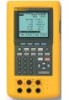
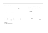
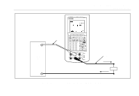
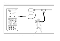
744 Users Manual Supplying Loop Power The calibrator supplies loop power at 28 V or 24 V dc through an internal series resistance of 250 Ω. The 28 V setting supplies enough current for two or three 4-20 mA devices on the loop in addition to the twowire transmitter but uses more battery power. Use the 24 V setting if there are two or fewer devices on the loop in addition to the two-wire transmitter. (Each device on a typical 4- to 20-mA loop has a resistance of 250 Ω, thus dropping 5 V at 20 mA. A typical transmitter must have 11 V minimum in order to operate correctly at its top end.) When loop power is enabled, the mA (middle column) jacks are dedicated to sourcing and measuring the current loop. This means that the SOURCE mA, measure RTD, and measure Ω functions are not available (see Table 8, later in this manual.) Connect the calibrator in series with the instrument current loop as Figure 18 shows. Proceed as follows to source loop power: 1. Press e for Setup mode. 2. Note that following Loop Power, Disabled is highlighted. Press e. 3. Use the u or d arrow keys to select Enabled 24 V or Enabled 28 V. 4. Press e. 5. Press the Done softkey. 50
-
 1
1 -
2
-
3
-
4
-
5
-
6
-
7
-
8
-
9
-
10
-
11
-
12
-
13
-
14
-
15
-
16
-
17
-
18
-
19
-
20
-
21
-
22
-
23
-
24
-
25
-
26
-
27
-
28
-
29
-
30
-
31
-
32
-
33
-
34
-
35
-
36
-
37
-
38
-
39
-
40
-
41
-
42
-
43
-
44
-
45
-
46
-
47
-
48
-
49
-
50
-
51
-
52
-
53
-
54
-
 55
55 -
 56
56 -
 57
57 -
 58
58 -
 59
59 -
 60
60 -
 61
61 -
 62
62 -
 63
63 -
 64
64 -
 65
65 -
66
-
67
-
68
-
69
-
70
-
71
-
72
-
73
-
74
-
75
-
76
-
77
-
78
-
79
-
80
-
81
-
82
-
83
-
84
-
85
-
86
-
87
-
88
-
89
-
90
-
91
-
92
-
93
-
94
-
95
-
96
-
97
-
98
-
99
-
100
-
101
-
102
-
103
-
104
-
105
-
106
-
107
-
108
-
109
-
110
-
111
-
112
-
113
-
114
-
115
-
116
-
117
-
118
-
119
-
120
-
121
-
122
-
123
-
124
-
125
-
126
-
127
-
128
-
129
-
130
-
131
-
132
-
133
-
134
-
135
-
136
-
137
-
138
 |
 |