Fluke 8845A FE 8845A & 8846A Users Manual - Page 71
Measuring Current, Function modifiers, Input
 |
View all Fluke 8845A manuals
Add to My Manuals
Save this manual to your list of manuals |
Page 71 highlights
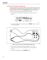
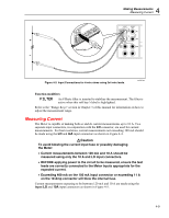
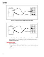
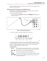
Ground tab 4 Making Measurements Measuring Current INPUT V 2W/4W HI SENSE 4W HI 1000 V CAT I 600V CAT II 300 V LO LO 1V FUSED 100 mA 10 A REAR FRONT Figure 4-3. Input Connections for 4-wire ohms using 2x4 wire leads. caw060.eps Function modifiers: FILTER An 8 Hertz filter is inserted to stabilize the measurement. The filter is active when this soft key's label is highlighted. Refer to the "Range Keys" section in Chapter 3 of this manual for information on how to adjust the measurement range. Measuring Current The Meter is capable of making both ac and dc current measurements up to 10 A. Two separate input connectors, in conjunction with the LO connector, are used for current measurements. For best resolution, current measurements not exceeding 100 mA should be made using the LO and mA input connectors as shown in Figure 4-4. WCaution To avoid blowing the current input fuse or possibly damaging the Meter: • Current measurements between 120 mA and 10 A should be measured using only the 10 A and LO input connectors. • BEFORE applying power to the circuit to be measured, ensure the test leads are correctly connected to the Meter inputs appropriate for the expected current. • Exceeding 400 mA on the 100 mA input connector or exceeding 11 A on the 10 Amp connector will blow the internal fuse. Current measurements expecting to be between 120 mA and 10 A are made using the Input LO and 10A input connectors as shown in Figure 4-5. 4-9
-
 1
1 -
2
-
3
-
4
-
5
-
6
-
7
-
8
-
9
-
10
-
11
-
12
-
13
-
14
-
15
-
16
-
17
-
18
-
19
-
20
-
21
-
22
-
23
-
24
-
25
-
26
-
27
-
28
-
29
-
30
-
31
-
32
-
33
-
34
-
35
-
36
-
37
-
38
-
39
-
40
-
41
-
42
-
43
-
44
-
45
-
46
-
47
-
48
-
49
-
50
-
51
-
52
-
53
-
54
-
55
-
56
-
57
-
58
-
59
-
60
-
61
-
62
-
63
-
64
-
65
-
 66
66 -
 67
67 -
 68
68 -
 69
69 -
 70
70 -
 71
71 -
 72
72 -
 73
73 -
 74
74 -
 75
75 -
 76
76 -
77
-
78
-
79
-
80
-
81
-
82
-
83
-
84
-
85
-
86
-
87
-
88
-
89
-
90
-
91
-
92
-
93
 |
 |
