Fluke 8845A FE 8845A & 8846A Users Manual - Page 79
Connecting an External Trigger, Monitoring the Measurement-Complete Signal
 |
View all Fluke 8845A manuals
Add to My Manuals
Save this manual to your list of manuals |
Page 79 highlights
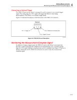
4 Making Measurements Monitoring the Measurement-Complete Signal Connecting an External Trigger The TRIG I/O jack on the Meter's rear panel is used to connect to an external trigger signal. The rising edge of a TTL signal will trigger the Meter to start taking measurements, if the Meter is in external trigger mode. Figure 4-9 indicates the purpose of the three pins in the TRIG I/O connector. TRIG I/O Pin 1: Trigger In Pin 3: Measure Complete Out Pin 2: Signal Ground Figure 4-9. TRIG I/O Pin-out Description caw059.eps Monitoring the Measurement-Complete Signal In addition to being a trigger input, the TRIG I/O jack on the Meter's rear panel also provides a signal indicating the completion of a measurement cycle. A positive going edge of a TTL signal indicates a measurement cycle is complete. See Figure 4-9 above to identify which pins on the TRIG I/O connector are used to sense the measurementcomplete signal. 4-17
-
 1
1 -
2
-
3
-
4
-
5
-
6
-
7
-
8
-
9
-
10
-
11
-
12
-
13
-
14
-
15
-
16
-
17
-
18
-
19
-
20
-
21
-
22
-
23
-
24
-
25
-
26
-
27
-
28
-
29
-
30
-
31
-
32
-
33
-
34
-
35
-
36
-
37
-
38
-
39
-
40
-
41
-
42
-
43
-
44
-
45
-
46
-
47
-
48
-
49
-
50
-
51
-
52
-
53
-
54
-
55
-
56
-
57
-
58
-
59
-
60
-
61
-
62
-
63
-
64
-
65
-
66
-
67
-
68
-
69
-
70
-
71
-
72
-
73
-
 74
74 -
 75
75 -
 76
76 -
 77
77 -
 78
78 -
 79
79 -
 80
80 -
 81
81 -
 82
82 -
 83
83 -
 84
84 -
85
-
86
-
87
-
88
-
89
-
90
-
91
-
92
-
93
 |
 |
