Fluke 8845A FE 8845A & 8846A Users Manual - Page 77
Making a Triggered Measurement
 |
View all Fluke 8845A manuals
Add to My Manuals
Save this manual to your list of manuals |
Page 77 highlights
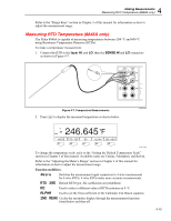
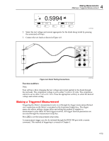
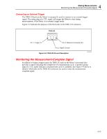
4 Making Measurements Making a Triggered Measurement + 0.5994 F1 F2 F3 F4 F5 caw13f.eps 2. Select the test voltage and current appropriate for the diode being tested by pressing the associated soft keys. 3. Connect the test leads as shown in Figure 4-8. INPUT V 2W/4W HI SENSE 4W HI 1000 V CAT I 600V CAT II 300 V LO LO 1V FUSED 100 mA 10 A REAR FRONT Figure 4-8. Diode Testing Connections caw024.eps Function modifiers: None Four soft keys allow changing the test voltage and current applied to the diode through the test leads. The compliance voltage is set to either 5 volts or 10 volts. The compliance current is set to either 1 mA or 0.1 mA. Press the appropriate soft key to select the desired voltage and current setting. Making a Triggered Measurement Triggering the Meter's measurement cycle is set through the trigger menu and performed via a connection on the Meter's rear panel or the front panel trigger key. The trigger menu also allows setting a trigger delay and setting the number of samples or measurement cycles taken for each trigger received. All trigger function parameters are accessed through the measurement setup key. Press Lto see the measurement setup menu. A measurement trigger can also be initiated through the IEEE 488 port with a remote command. This method of triggering is covered in Chapter 5. 4-15
-
 1
1 -
2
-
3
-
4
-
5
-
6
-
7
-
8
-
9
-
10
-
11
-
12
-
13
-
14
-
15
-
16
-
17
-
18
-
19
-
20
-
21
-
22
-
23
-
24
-
25
-
26
-
27
-
28
-
29
-
30
-
31
-
32
-
33
-
34
-
35
-
36
-
37
-
38
-
39
-
40
-
41
-
42
-
43
-
44
-
45
-
46
-
47
-
48
-
49
-
50
-
51
-
52
-
53
-
54
-
55
-
56
-
57
-
58
-
59
-
60
-
61
-
62
-
63
-
64
-
65
-
66
-
67
-
68
-
69
-
70
-
71
-
 72
72 -
 73
73 -
 74
74 -
 75
75 -
 76
76 -
 77
77 -
 78
78 -
 79
79 -
 80
80 -
 81
81 -
 82
82 -
83
-
84
-
85
-
86
-
87
-
88
-
89
-
90
-
91
-
92
-
93
 |
 |
