Fluke P3011-MMHG Product Manual - Page 34
System Selector Valve, Disassembly, Cleaning & Inspection
 |
View all Fluke P3011-MMHG manuals
Add to My Manuals
Save this manual to your list of manuals |
Page 34 highlights
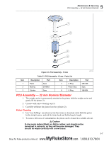
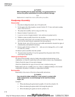
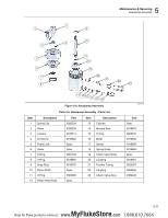
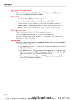
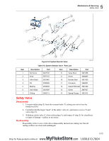
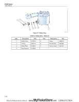
P3000 Series Users Manual System Selector Valve Before commencing disassembly of the selector valve, make a note of the tubing connections to avoid problems during reassembly. Disassembly 1. Disconnect nylon tubing from connectors (11). 2. Loosen set screws (1), and remove knob (2) from valve shaft (3). 3. Remove screws (13), and withdraw valve assembly from support bracket (12). 4. Remove screw (9), and lift off valve rotor (8), taking care not to lose O rings (7). 5. Withdraw shaft (3) from valve body (6), taking care not to lose bearings (5). Cleaning & Inspection The bearings (5) are sealed, and should not require maintenance. Check O-rings and all sealing faces for signs of wear and/or damage. If necessary, the valve body can be immersed in a solvent, but it must be thoroughly cleaned and dry before reassembly. Re-Assembly Reassembly is the reverse of removal. Care must be taken to ensure that the components are located correctly, in particular: • The relationship between the pins (4) in the valve shaft (3) and the valve body (6), which limit rotation. • The orientation of the grooves on valve rotor (8) and the pin (4) in the valve shaft (3). These grooves align with the spring plunger (14) in the support bracket (12) when fully assembled, and ensure correct valve operation. • The orientation of the knob (2), as the "P-V" label on the front should be the correct way up when fully assembled. 5-12 MyFlukeStore Shop for Fluke products online at: www. .com 1.888.610.7664
-
 1
1 -
2
-
3
-
4
-
5
-
6
-
7
-
8
-
9
-
10
-
11
-
12
-
13
-
14
-
15
-
16
-
17
-
18
-
19
-
20
-
21
-
22
-
23
-
24
-
25
-
26
-
27
-
28
-
 29
29 -
 30
30 -
 31
31 -
 32
32 -
 33
33 -
 34
34 -
 35
35 -
 36
36 -
 37
37 -
 38
38 -
 39
39 -
40
-
41
 |
 |