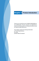
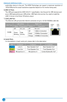
Foxconn D180S-D User Manual - Page 11
Layout, Front Audio Header, PCI Express X16 Slot, 4-pin ATX 12V Power Connector
 |
View all Foxconn D180S-D manuals
Add to My Manuals
Save this manual to your list of manuals |
Page 11 highlights
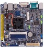
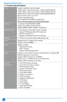
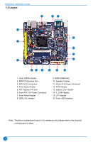
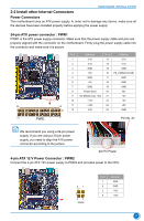
PRODUCT INTRODUCTION 1-2 Layout 3 2 1 4 16 5 15 14 13 6 7 8 9 10 11 12 1. Clear CMOS Header 2. MINI PCI Express Slot 3. SATA 2.0 Connectors 4. Front Audio Header 5. PCI Express X16 Slot 6. 4-pin ATX 12V Power Connector 7. Front Panel Header 8. DDR_VSL Header 9. DDR3 DIMM Slot 10. Speaker Header 11. 24-pin ATX Power Connector 12. INTR Header 13. System_Fan Header 14. F_COM Header 15. LPT Header 16. Front USB Headers Note : The above motherboard layout is for reference only, please refer to the physical motherboard for detail. 4
-
 1
1 -
2
-
3
-
4
-
5
-
 6
6 -
 7
7 -
 8
8 -
 9
9 -
 10
10 -
 11
11 -
 12
12 -
 13
13 -
 14
14 -
 15
15 -
 16
16 -
17
-
18
-
19
-
20
-
21
-
22
-
23
-
24
-
25
-
26
-
27
-
28
-
29
-
30
-
31
-
32
-
33
-
34
-
35
-
36
-
37
-
38
-
39
-
40
-
41
-
42
-
43
-
44
-
45
-
46
-
47
-
48
-
49
-
50
-
51
-
52
-
53
-
54
-
55
-
56
-
57
-
58
-
59
-
60
-
61
-
62
-
63
-
64
-
65
 |
 |
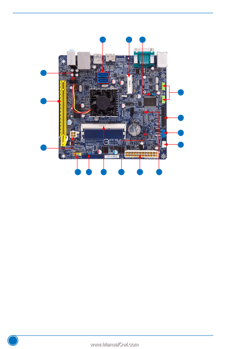
PRODUCT INTRODUCTION
4
1-2 Layout
Note : The above motherboard layout is for reference only, please refer to the physical
motherboard for detail.
1. Clear CMOS Header
2. MINI PCI Express Slot
3. SATA 2.0 Connectors
4. Front Audio Header
5. PCI Express X16 Slot
6. 4-pin ATX 12V Power Connector
7. Front Panel Header
8. DDR_VSL Header
9. DDR3 DIMM Slot
10. Speaker Header
11. 24-pin ATX Power Connector
12. INTR Header
13. System_Fan Header
14.
F_COM Header
15.
LPT Header
16. Front USB Headers
11
10
2
3
4
6
7
9
8
5
14
15
16
13
12
1