Foxconn D180S-D User Manual - Page 18
Front Panel Header : FP1, LPT Hearder : LPT, Hard Disk LED Connector HDD-LED, Reset Switch RESET-SW
 |
View all Foxconn D180S-D manuals
Add to My Manuals
Save this manual to your list of manuals |
Page 18 highlights
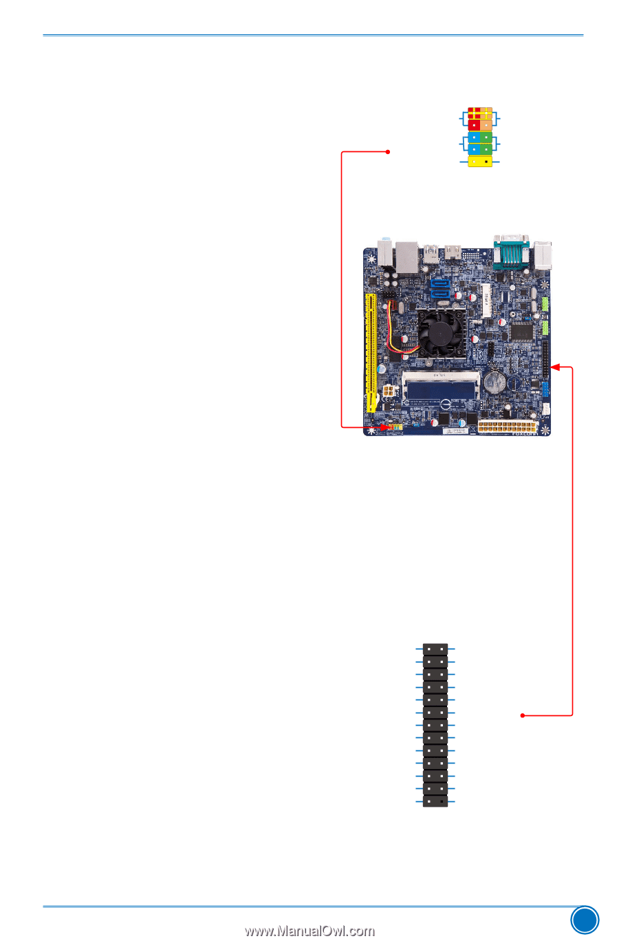
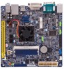
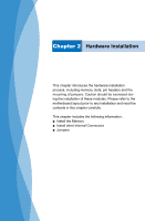
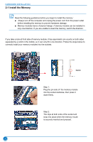
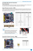
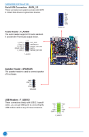
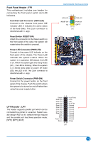
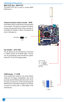
Front Panel Header : FP1 This motherboard includes one header for connecting the front panel switch and LED Indicators. Hard Disk LED Connector (HDD-LED) Connect to the chassis front panel IDE indicator LED. It indicates the active status of the hard disks. This 2-pin connector is directional with +/- sign. Reset Switch (RESET-SW) Attach the connector to the Reset switch on the front panel of the case; the system will restart when the switch is pressed. Power LED Connector (PWR-LED) Connect to the power LED indicator on the front panel of the chassis. The Power LED indicates the system's status. When the system is in operation (S0 status), the LED is on. When the system gets into sleep mode (S1) , the LED is blinking; When the system is in S3/S4 sleep state or power off mode (S5), the LED is off. This 2-pin connector is directional with +/- sign. Power Switch Connector (PWR-SW) Connect to the power button on the front panel of the chassis. Push this switch allows the system to be turned on and off rather than using the power supply button. LPT Hearder : LPT The header supports parallel port which can be connected to a printer or a scanner. System usually assign IRQ7 as it's default interrupt request and the parallel port has three operation mode: [SPP], [EPP], [ECP]. HARDWARE INSTALLATION 12 + + HDD-LED - PWR-LED - RESET-SW PWR-SW NC EMPTY 9 10 FP1 Strobe Data it [0] Data it [1] Data it [2] Data it [3] Data it [4] Data it [5] Data it [6] Data it [7] ACK Busy Paper End Select 12 25 26 LPT Auto Feed Error INIT SLCT IN Ground Ground Ground Ground Ground Ground Ground Ground Empty 11
-
 1
1 -
2
-
3
-
4
-
5
-
6
-
7
-
8
-
9
-
10
-
11
-
12
-
 13
13 -
 14
14 -
 15
15 -
 16
16 -
 17
17 -
 18
18 -
 19
19 -
 20
20 -
 21
21 -
 22
22 -
 23
23 -
24
-
25
-
26
-
27
-
28
-
29
-
30
-
31
-
32
-
33
-
34
-
35
-
36
-
37
-
38
-
39
-
40
-
41
-
42
-
43
-
44
-
45
-
46
-
47
-
48
-
49
-
50
-
51
-
52
-
53
-
54
-
55
-
56
-
57
-
58
-
59
-
60
-
61
-
62
-
63
-
64
-
65
 |
 |