Fujitsu MAP3367NC Manual/User Guide - Page 62
in SCSI Physical Interface Specifications., Delay time] = [SCSI ID]
 |
UPC - 000004119623
View all Fujitsu MAP3367NC manuals
Add to My Manuals
Save this manual to your list of manuals |
Page 62 highlights
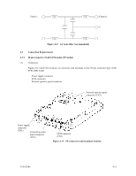
(4) Sequential starting of spindle motors After power is turned on to the IDD, a large amount of current flows in the +12 VDC line when the spindle motor rotation starts. Therefore, if more than one IDD is used, the spindle motors should be started sequentially using one of the following procedures to prevent overload of the power supply unit. For the NP model drives, the spindle motors should be started by the following procedures. Regarding how to set a spindle motor start control mode, see Subsection 5.3.2. a) Issue START/STOP commands at more than 12-second intervals to start the spindle motors. For details of this command specification, refer to SCSI Logical Interface Specifications. b) Turn on the +12 VDC power in the power supply unit at more than 12-second intervals to start the spindle motors sequentially. For the NC model drives, the spindle motors should be started after a delay of the following time. [Delay time] = [SCSI ID] × 12 seconds SCSI ID 0 1 2... 15 Delay time of spindle motor starting 0 12 s 24 ...s 180 s (5) Power supply to SCSI terminating resistor If power for the terminating resistor is supplied from the IDD to other SCSI devices through the SCSI bus, the current-carrying capacity of the +5 VDC power supply line to the IDD must be designed with considering of an increase of up to 200 mA. A method of power supply to the terminating resistor is selected with a setting terminal on the IDD (MP model only). See Subsection 5.3.2 for this selection. For the electrical condition of supplying power to the terminating resistor, refer to Subsection 1.4.2 in SCSI Physical Interface Specifications. (6) Noise filter To eliminate AC line noise, a noise filter should be installed at the AC input terminal on the IDD power supply unit. The specification of this noise filter is as follows: • Attenuation: 40 dB or more at 10 MHz • Circuit construction: T-configuration as shown in Figure 4.12 is recommended. 4-10 C141-E166
-
 1
1 -
2
-
3
-
4
-
5
-
6
-
7
-
8
-
9
-
10
-
11
-
12
-
13
-
14
-
15
-
16
-
17
-
18
-
19
-
20
-
21
-
22
-
23
-
24
-
25
-
26
-
27
-
28
-
29
-
30
-
31
-
32
-
33
-
34
-
35
-
36
-
37
-
38
-
39
-
40
-
41
-
42
-
43
-
44
-
45
-
46
-
47
-
48
-
49
-
50
-
51
-
52
-
53
-
54
-
55
-
56
-
 57
57 -
 58
58 -
 59
59 -
 60
60 -
 61
61 -
 62
62 -
 63
63 -
 64
64 -
 65
65 -
 66
66 -
 67
67 -
68
-
69
-
70
-
71
-
72
-
73
-
74
-
75
-
76
-
77
-
78
-
79
-
80
-
81
-
82
-
83
-
84
-
85
-
86
-
87
-
88
-
89
-
90
-
91
-
92
-
93
-
94
-
95
-
96
-
97
-
98
-
99
-
100
-
101
-
102
-
103
-
104
-
105
-
106
-
107
-
108
-
109
-
110
-
111
-
112
-
113
-
114
-
115
-
116
-
117
-
118
-
119
-
120
-
121
-
122
-
123
-
124
-
125
-
126
-
127
-
128
-
129
-
130
-
131
-
132
 |
 |
