Fujitsu MAP3367NC Manual/User Guide - Page 85
Connecting Cables, attention to the inserting orientation of each cable connector.
 |
UPC - 000004119623
View all Fujitsu MAP3367NC manuals
Add to My Manuals
Save this manual to your list of manuals |
Page 85 highlights
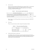
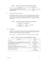
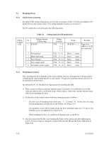
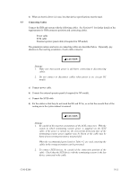
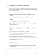
4) When an electric driver is in use, less than device specifications must be used. 5.5 Connecting Cables Connect the IDD and system with the following cables. See Section 4.3 for further details of the requirements for IDD connector positions and connecting cables. • Power cable • SCSI cable • External operator panel cable (if required for NP model) The general procedures and notes on connecting cables are described below. Especially, pay attention to the inserting orientation of each cable connector. CAUTION Damage 1. Make sure that system power is off before connecting or disconnecting cables. 2. Do not connect or disconnect cables when power is on. (except NC model) a) Connect power cable. b) Connect the external operator panel (if required for NP model). c) Connect the SCSI cable. d) Fix the cables so that they do not touch the DE and PCAs, or so that the smooth flow of the cooling air in the system cabinet is assured. CAUTION Damage 1. Be careful of the insertion orientations of the SCSI connectors. With the system in which terminating resistor power is supplied via the SCSI cable, if the power is turned on, the overcurrent protection fuse of the terminating resistor power supplier may be blown or the cable may be burnt if overcurrent protection is not provided. When the recommended parts listed in Table 4.2 are used, inserting the cables in the wrong orientation can be prevented. 2. To connect SCSI devices, be careful of the connection position of the cable. Check that the SCSI device with the terminating resistor is the last device connected to the cable. C141-E166 5-11
-
 1
1 -
2
-
3
-
4
-
5
-
6
-
7
-
8
-
9
-
10
-
11
-
12
-
13
-
14
-
15
-
16
-
17
-
18
-
19
-
20
-
21
-
22
-
23
-
24
-
25
-
26
-
27
-
28
-
29
-
30
-
31
-
32
-
33
-
34
-
35
-
36
-
37
-
38
-
39
-
40
-
41
-
42
-
43
-
44
-
45
-
46
-
47
-
48
-
49
-
50
-
51
-
52
-
53
-
54
-
55
-
56
-
57
-
58
-
59
-
60
-
61
-
62
-
63
-
64
-
65
-
66
-
67
-
68
-
69
-
70
-
71
-
72
-
73
-
74
-
75
-
76
-
77
-
78
-
79
-
 80
80 -
 81
81 -
 82
82 -
 83
83 -
 84
84 -
 85
85 -
 86
86 -
 87
87 -
 88
88 -
 89
89 -
 90
90 -
91
-
92
-
93
-
94
-
95
-
96
-
97
-
98
-
99
-
100
-
101
-
102
-
103
-
104
-
105
-
106
-
107
-
108
-
109
-
110
-
111
-
112
-
113
-
114
-
115
-
116
-
117
-
118
-
119
-
120
-
121
-
122
-
123
-
124
-
125
-
126
-
127
-
128
-
129
-
130
-
131
-
132
 |
 |