Fujitsu MAP3367NC Manual/User Guide - Page 65
External operator panel connector CN1
 |
UPC - 000004119623
View all Fujitsu MAP3367NC manuals
Add to My Manuals
Save this manual to your list of manuals |
Page 65 highlights
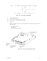
(3) SG terminal The IDD is not provided with an SG terminal (fasten tab) for DC grounding. Therefore, when connecting SG and FG in the system, use the +5 VDC RETURN (ground) inside the power supply connector as the SG on the power supply side. (4) Connector for external operator panel • Connector for 16-bit SCSI external operator panel CN1 provides connector for the external operator panel other than the SCSI bus as shown in Figure 4.16. Also, a connector for the external operator panel are provided on the IDD as shown in Figure 4.17. This allows connection of an external LED on the front panel, and an SCSI ID setting switch. For the recommended circuit of the external operator panel, see Subsection 4.3.4. Pin Signal A1 -ID0 A2 Fault LED A3 -ID1 A4 ESID A5 -ID2 A6 (Reserved) A7 -ID3 A8 -LED A9 OPEN A10 GND A11 +5 V A12 -WTP Figure 4.16 External operator panel connector (CN1) C141-E166 4-13
-
 1
1 -
2
-
3
-
4
-
5
-
6
-
7
-
8
-
9
-
10
-
11
-
12
-
13
-
14
-
15
-
16
-
17
-
18
-
19
-
20
-
21
-
22
-
23
-
24
-
25
-
26
-
27
-
28
-
29
-
30
-
31
-
32
-
33
-
34
-
35
-
36
-
37
-
38
-
39
-
40
-
41
-
42
-
43
-
44
-
45
-
46
-
47
-
48
-
49
-
50
-
51
-
52
-
53
-
54
-
55
-
56
-
57
-
58
-
59
-
 60
60 -
 61
61 -
 62
62 -
 63
63 -
 64
64 -
 65
65 -
 66
66 -
 67
67 -
 68
68 -
 69
69 -
 70
70 -
71
-
72
-
73
-
74
-
75
-
76
-
77
-
78
-
79
-
80
-
81
-
82
-
83
-
84
-
85
-
86
-
87
-
88
-
89
-
90
-
91
-
92
-
93
-
94
-
95
-
96
-
97
-
98
-
99
-
100
-
101
-
102
-
103
-
104
-
105
-
106
-
107
-
108
-
109
-
110
-
111
-
112
-
113
-
114
-
115
-
116
-
117
-
118
-
119
-
120
-
121
-
122
-
123
-
124
-
125
-
126
-
127
-
128
-
129
-
130
-
131
-
132
 |
 |
