Garmin Edge 305CAD Owner's Manual - Page 16
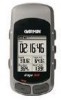
Position the GSC10 Sensor, To install the GSC10 - speed cadence sensor
 |
UPC - 753759051716
View all Garmin Edge 305CAD manuals
Add to My Manuals
Save this manual to your list of manuals |
Page 16 highlights
GETTING STARTED Position the GSC10 Sensor NOTE: The GSC10 is an accessory for the Edge 305 only. To install the GSC10: 1. Place the GSC10 on the rear chain stay (on the side opposite of the drive train). Loosely attach the GSC10 The Edge 305 CAD includes a using two cable ties. wireless speed and cadence sensor. Both magnets must be aligned with their respective indication lines for the Edge to receive data. 1 GSC10 on rear chain stay reset button indication line cable ties 16 Edge™ 205/305 Owner's Manual
-
 1
1 -
2
-
3
-
4
-
5
-
6
-
7
-
8
-
9
-
10
-
 11
11 -
 12
12 -
 13
13 -
 14
14 -
 15
15 -
 16
16 -
 17
17 -
 18
18 -
 19
19 -
 20
20 -
 21
21 -
22
-
23
-
24
-
25
-
26
-
27
-
28
-
29
-
30
-
31
-
32
-
33
-
34
-
35
-
36
-
37
-
38
-
39
-
40
-
41
-
42
-
43
-
44
-
45
-
46
-
47
-
48
-
49
-
50
-
51
-
52
-
53
-
54
-
55
-
56
-
57
-
58
-
59
-
60
-
61
-
62
-
63
-
64
-
65
-
66
-
67
-
68
-
69
-
70
-
71
-
72
-
73
-
74
-
75
-
76
-
77
-
78
-
79
-
80
-
81
-
82
-
83
-
84
-
85
-
86
-
87
-
88
-
89
-
90
-
91
-
92
-
93
-
94
 |
 |

16
Edge
™
205/305 Owner’s Manual
G
ETTING
S
TARTED
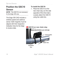
Position the GSC10
Sensor
NOTE:
The GSC10 is an accessory
for the Edge 305 only.
The Edge 305 CAD includes a
wireless speed and cadence
sensor. Both magnets must be
aligned with their respective
indication lines for the Edge
to receive data.
To install the GSC10:
1. Place the GSC10 on the
rear chain stay (on the side
opposite of the drive train).
Loosely attach the GSC10
using two cable ties.
reset button
cable ties
indication
line
GSC10 on rear chain stay
1