Garmin GTX 32 Installation Manual - Page 15
INSTALLATION OVERVIEW, Introduction, Installation Materials, Catalog Part Number, Equipment
 |
View all Garmin GTX 32 manuals
Add to My Manuals
Save this manual to your list of manuals |
Page 15 highlights
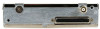
2 INSTALLATION OVERVIEW 2.1 Introduction This section provides hardware equipment information for installing the GTX 32 Transponder, related hardware and optional accessories. Installation of the GTX 32 should follow the data detailed in this manual. Cabling is fabricated by the installing agency to fit each particular aircraft. The guidance of FAA advisory circulars AC 43.13-1B and AC 43.13-2A, where applicable, may be found useful for making retro-fit installations that comply with FAA regulations. Refer to the G1000 System Installation Manual, Garmin part number 190-00303-00 for further details on the mechanical aspects. For installation in an aircraft using the remote mounted stand-alone rack refer to Appendix B for rack drawings and dimensions. 2.2 Installation Materials The GTX 32 is available as a single unit under the following part numbers: Item GTX 32 (011-00768-00) Catalog Part Number 010-00265-00 2.2.1 Equipment Available Each of the following accessories is provided separately for the GTX 32 unit and is required for installation. Item Garmin Catalog Part Number G1000 Install Rack, GTX 32 115-00439-00 G1000 Nutplate Kit 011-00915-01 (preferred) or 011-01148-01 Or GTX 32 Remote Stand-Alone Install Rack (Alternate Configuration) 115-00628-00 Connector Kit, GTX 32 011-01013-00 (SPIDER) or 011-01013-01 (Shield Block) Backplate Assembly, GTX 32 011-00677-01 Garmin Transponder Antenna kit* 010-10160-00 *Note: A transponder antenna approved to TSO C66( ) or C74( ) that has been installed to meet the requirements of this manual may be used with the GTX 32. GTX 32 Installation Manual 190-00303-60 Page 2-1 Revision F
-
 1
1 -
2
-
3
-
4
-
5
-
6
-
7
-
8
-
9
-
 10
10 -
 11
11 -
 12
12 -
 13
13 -
 14
14 -
 15
15 -
 16
16 -
 17
17 -
 18
18 -
 19
19 -
 20
20 -
21
-
22
-
23
-
24
-
25
-
26
-
27
-
28
-
29
-
30
-
31
-
32
-
33
-
34
-
35
-
36
-
37
-
38
-
39
-
40
-
41
-
42
-
43
-
44
-
45
 |
 |
