Garmin GTX 32 Installation Manual - Page 24
NOTES, Backshell Assembly
 |
View all Garmin GTX 32 manuals
Add to My Manuals
Save this manual to your list of manuals |
Page 24 highlights
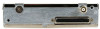
NOTES 1. Insertion/Extraction tools from ITT Cannon are all plastic; others are plastic with metal tip. 2. Non-Garmin part numbers shown are not maintained by Garmin and consequently are subject to change without notice. 3. Alternate contacts for 18 AWG wire: As an alternative to the Positronic contacts listed (and provided in the installation kit), the installer may use contacts made by ITT Cannon under P/N 031-1007-001. These contacts require the use of a different crimp tool positioner than shown in the table, with the part numbers as follows: Daniels P/N K250, Astro P/N 616245, or ITT Cannon P/N 980-0005-722. 4. Extracting the #16, #18 and #20 contact requires that the expanded wire barrel be cut off from the contact. It may also be necessary to push the pin out from the face of the connector when using an extractor due to the absence of the wire. A new contact must be used when reassembling the connector. 5. For applications using 16 AWG wire, contact Garmin for information regarding connector crimp positioner tooling. 6. All wires must be passed through the backshell before being assembled to connector. 3.3 Backshell Assembly The GTX 32 connector kit includes one Garmin backshell assembly. Garmin's backshell connectors give the installer the ability to quickly and easily terminate shield grounds at the backshell housing using one of two methods available (SPIDER or Shield Block). NOTE The SPIDER grounding method is permitted for previous installations; however Garmin recommends the use of the Shield Block grounding method for all new installations. Garmin Integrated Flight Deck Installations: To assemble the backshell and grounding system, refer to instructions provided in the G1000 System Installation Manual (190-00303-00), as well as the SPIDER Installation Instructions (190-00313-02) and Shield Block Installation Instructions (190-00313-09). Non- Garmin Integrated Flight Deck Installations: GTX 32 installations that are not installed with the Garmin Integrated Flight Deck, the connector and backshell assembly is shown in Figure 3-1. Refer to the SPIDER Installation Instructions (190-00313-02) and Shield Block Installation Instructions (190-00313-09) for grounding instructions. 1. Backshell Cast Housing. Provides a mounting point for connector accessories. 2. D-Subminiature 25 pin connector. 3. Ground System (SPIDER ground shown). Allows shield grounds to be made to the backshell housing. 4. Strain Relief Tab. Fastens wiring bundle to housing. 5. Backshell Lid. Provides access when servicing the connector. Page 3-2 Revision F GTX 32 Installation Manual 190-00303-60
-
 1
1 -
2
-
3
-
4
-
5
-
6
-
7
-
8
-
9
-
10
-
11
-
12
-
13
-
14
-
15
-
16
-
17
-
18
-
 19
19 -
 20
20 -
 21
21 -
 22
22 -
 23
23 -
 24
24 -
 25
25 -
 26
26 -
 27
27 -
 28
28 -
 29
29 -
30
-
31
-
32
-
33
-
34
-
35
-
36
-
37
-
38
-
39
-
40
-
41
-
42
-
43
-
44
-
45
 |
 |
