Garmin GTX 32 Installation Manual - Page 7

List Of Illustrations, List Of Tables - transponder

Page 7 highlights

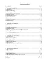
LIST OF ILLUSTRATIONS FIGURE PAGE 2-1 Antenna Installation Considerations 2-3 2-2 GTX 32 G1000 Unit Rack ...2-7 2-3 GTX 32 Remote Stand-Alone Rack 2-7 2-4 GTX 32 Remote Stand-Alone Rack, Suggested Mounting Locations 2-8 3-1 Backshell Connector Assembly ...3-3 4-1 Rear Connector, J3271...4-1 4-2 GTX 32, Software Update Connections 4-5 A-1 Upward Static Load Test ...A-2 A-2 Forward Static Load Test...A-2 B-1 GTX 32 Outline Drawing, in G1000 Rack B-1 B-2 GTX 32 G1000 Rack/Connector Assembly Drawing B-3 B-3 GTX 32 Remote Mounted Stand-Alone Rack/Connector Assembly Drawing (Sheet 1 of 2).......... B-5 B-3 GTX 32 Remote Mounted Stand-Alone Rack/Connector Assembly Drawing (Sheet 2 B-7 C-1 GTX 32 Typical Garmin Integrated Flight Deck System Interconnect Wiring Diagram C-1 C-2 GTX 32 to GNS 480 (CNX80) Interconnect Wiring Diagram C-3 C-3 GTX 32 to GDL 90, Typical Interconnect Wiring Diagram C-5 C-4 Dual GTX 32 Transponders, Single Altitude Encoder, Interconnect Wiring Diagram (Sheet 1 of 2)...C-7 C-4 Dual GTX 32 Transponders, Single Altitude Encoder, Interconnect Wiring Diagram (Sheet 2)...C-9 LIST OF TABLES TABLE PAGE 3-1 Pin Contact Part Numbers...3-1 3-2 Recommended Crimp Tools ...3-1 3-3 Unit Power Loads ...3-4 4-1 P3271 Pin Assignments ...4-1 4-2 Aircraft Power Pin Assignments...4-2 4-3 Encoded Altitude Pin Assignments 4-3 4-4 Discrete Input/Output Pin Assignments 4-4 4-5 RS-232 Input/Output Pin Assignments 4-5 A-1 Static Test Load ...A-1 GTX 32 Installation Manual 190-00303-60 Page v Revision F

  • 1
  • 2
  • 3
  • 4
  • 5
  • 6
  • 7
  • 8
  • 9
  • 10
  • 11
  • 12
  • 13
  • 14
  • 15
  • 16
  • 17
  • 18
  • 19
  • 20
  • 21
  • 22
  • 23
  • 24
  • 25
  • 26
  • 27
  • 28
  • 29
  • 30
  • 31
  • 32
  • 33
  • 34
  • 35
  • 36
  • 37
  • 38
  • 39
  • 40
  • 41
  • 42
  • 43
  • 44
  • 45

GTX 32 Installation Manual
Page v
190-00303-60
Revision F
LIST OF ILLUSTRATIONS
FIGURE
PAGE
2-1 Antenna Installation Considerations
..................................................................................................
2-3
2-2 GTX 32 G1000 Unit Rack
.................................................................................................................
2-7
2-3 GTX 32 Remote Stand-Alone Rack
..................................................................................................
2-7
2-4
GTX 32 Remote Stand-Alone Rack, Suggested Mounting Locations
...............................................
2-8
3-1 Backshell Connector Assembly
.........................................................................................................
3-3
4-1 Rear Connector, J3271
.......................................................................................................................
4-1
4-2 GTX 32, Software Update Connections
............................................................................................
4-5
A-1 Upward Static Load Test
..................................................................................................................
A-2
A-2 Forward Static Load Test
..................................................................................................................
A-2
B-1 GTX 32 Outline Drawing, in G1000 Rack,
......................................................................................
B-1
B-2 GTX 32 G1000 Rack/Connector Assembly Drawing
......................................................................
B-3
B-3 GTX 32 Remote Mounted Stand-Alone Rack/Connector Assembly Drawing (Sheet 1 of 2)
..........
B-5
B-3 GTX 32 Remote Mounted Stand-Alone Rack/Connector Assembly Drawing (Sheet 2)
.................
B-7
C-1 GTX 32 Typical Garmin Integrated Flight Deck System Interconnect Wiring Diagram
.................
C-1
C-2 GTX 32 to GNS 480 (CNX80) Interconnect Wiring Diagram
........................................................
C-3
C-3 GTX 32 to GDL 90, Typical Interconnect Wiring Diagram
.............................................................
C-5
C-4 Dual GTX 32 Transponders, Single Altitude Encoder, Interconnect Wiring
Diagram (Sheet 1 of 2)
......................................................................................................................
C-7
C-4 Dual GTX 32 Transponders, Single Altitude Encoder, Interconnect Wiring
Diagram (Sheet 2)
.............................................................................................................................
C-9
LIST OF TABLES
TABLE
PAGE
3-1 Pin Contact Part Numbers
..................................................................................................................
3-1
3-2 Recommended Crimp Tools
..............................................................................................................
3-1
3-3 Unit Power Loads
..............................................................................................................................
3-4
4-1 P3271 Pin Assignments
.....................................................................................................................
4-1
4-2 Aircraft Power Pin Assignments
........................................................................................................
4-2
4-3 Encoded Altitude Pin Assignments
...................................................................................................
4-3
4-4 Discrete Input/Output Pin Assignments
.............................................................................................
4-4
4-5 RS-232 Input/Output Pin Assignments
..............................................................................................
4-5
A-1 Static Test Load
................................................................................................................................
A-1