Garmin GTX 32 Installation Manual - Page 23
INSTALLATION PROCEDURE, Unpacking Unit, Wiring Harness Installation, CAUTION
 |
View all Garmin GTX 32 manuals
Add to My Manuals
Save this manual to your list of manuals |
Page 23 highlights
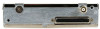
3 INSTALLATION PROCEDURE 3.1 Unpacking Unit Carefully unpack the equipment and make a visual inspection of the unit for evidence of damage incurred during shipment. If the unit is damaged, notify the carrier and file a claim. To justify a claim, save the original shipping container and all packing materials. Do not return the unit to Garmin until the carrier has authorized the claim. Retain the original shipping containers for storage. If the original containers are not available, a separate cardboard container should be prepared that is large enough to accommodate sufficient packing material to prevent movement. 3.2 Wiring Harness Installation Allow adequate space for installation of cables and connectors. The installer shall supply and fabricate all cables. All electrical connections to the GTX 32 are made through one 25-pin D-subminiature connector. Section 4 defines the electrical characteristics of all input and output signals. Required connectors and associated hardware are supplied with the connector kit. See Appendix C for examples of interconnect wiring diagrams. Construct the actual harnesses in accordance with the aircraft manufacturer authorized interconnect standards. CAUTION Check wiring connections for errors before inserting the GTX 32 into the rack. Incorrect wiring could cause internal component damage. Manufacturer Garmin P/N Military P/N AMP Positronic ITT Cannon Table 3-1 Pin Contact Part Numbers 25 pin D-Subminiature connector (P3271) 18 AWG 20-24 AWG (Power Only) 336-00023-00 336-00022-00 N/A M39029/63-368 N/A 205090-1 FC6018D M39029/63-368 See Note 3 031-1007-42 Table 3-2 Recommended Crimp Tools Manufacturer Hand Crimping Tool 18 AWG Positioner Insertion/ Extraction Tool 20-24 AWG Positioner Insertion/ Extraction Tool Military P/N Positronic ITT Cannon AMP Daniels Astro M22520/2-01 9507 995-0001-584 601966-1 AFM8 615717 N/A 9502-11 N/A N/A K774 N/A M81969/1-02 M81969/1-02 N/A N/A M81969/1-02 M81969/1-02 M22520/2-08 9502-5 995-0001-604 601966-5 K13-1 615724 M81969/1-02 M81969/1-02 980-2000-426 91067-2 M24308/1-02 M81969/1-02 GTX 32 Installation Manual 190-00303-60 Page 3-1 Revision F
-
 1
1 -
2
-
3
-
4
-
5
-
6
-
7
-
8
-
9
-
10
-
11
-
12
-
13
-
14
-
15
-
16
-
17
-
 18
18 -
 19
19 -
 20
20 -
 21
21 -
 22
22 -
 23
23 -
 24
24 -
 25
25 -
 26
26 -
 27
27 -
 28
28 -
29
-
30
-
31
-
32
-
33
-
34
-
35
-
36
-
37
-
38
-
39
-
40
-
41
-
42
-
43
-
44
-
45
 |
 |
