Garmin GTX 32 Installation Manual - Page 26
Electrical Load Analysis, Circuit Breaker Placard, Final Installation, CAUTION
 |
View all Garmin GTX 32 manuals
Add to My Manuals
Save this manual to your list of manuals |
Page 26 highlights
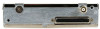
3.5 Electrical Load Analysis An electrical load analysis should be completed on each aircraft prior to installation in accordance with AC43.13-1B, Chapter 11. See Section 1.6.3 for Power Requirements. Use the following values for Power Loads computation: GTX 32 Input GTX 32 Main Power Table 3-3. Unit Power Loads 1 14 VDC 2 Typical Max. 28 VDC Typical Max. 1.1 A 1.85 A 0.6 A 0.9 A 3.5.1 Circuit Breaker Placard Install a Circuit Breaker Placard labeled Transponder or Transponder 1, Transponder 2 as appropriate as indicated in AC 43.13-2A, Paragraph 27c(4). 3.6 Final Installation For final installation and assembly, refer to the outline and installation drawings shown in Appendix B of this manual. 1. Assemble the connector backshell as described in Section 3.3. 2. Attach the connector to the rear plate using the screws provided in the connector kit. 3. Mount the unit rack to the main system rack or other suitable mounting location using the provided nutplates. 4. Assemble the rear plate into the GTX 32 unit rack. 5. Insert the GTX 32 into the rack, noting proper orientation as shown on the installation drawing in Appendix B. CAUTION Do not use excessive force when inserting the GTX 32 into the rack. This may cause damage to occur to the connectors, unit, and/or unit rack. If heavy resistance is felt during installation, stop! Remove the GTX 32 and identify the source of resistance. The rear plate is designed to float in the unit rack. Check to ensure the rear plate is not bound by the connector harness. 6. Lock the GTX 32 in place using the lever-locking handle. Fasten the handle to the GTX 32 body using the provided Phillips screw. (Note that some early GTX 32's use D-ring ¼-turn fastener) CAUTION Start the handle screw into the hole carefully, to avoid cross-threading. Do not apply torque in excess of 14 in-lbs to the handle screw. The application of torque exceeding 14 in-lbs to this screw will damage the LRU case and/or retaining hardware. Page 3-4 Revision F GTX 32 Installation Manual 190-00303-60
-
 1
1 -
2
-
3
-
4
-
5
-
6
-
7
-
8
-
9
-
10
-
11
-
12
-
13
-
14
-
15
-
16
-
17
-
18
-
19
-
20
-
 21
21 -
 22
22 -
 23
23 -
 24
24 -
 25
25 -
 26
26 -
 27
27 -
 28
28 -
 29
29 -
 30
30 -
 31
31 -
32
-
33
-
34
-
35
-
36
-
37
-
38
-
39
-
40
-
41
-
42
-
43
-
44
-
45
 |
 |
