Garmin GTX 32 Installation Manual - Page 32
Discrete Inputs/Outputs, Pin Name, Connector
 |
View all Garmin GTX 32 manuals
Add to My Manuals
Save this manual to your list of manuals |
Page 32 highlights
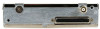
Only approved devices may provide altitude to the GTX 32 in accordance with 14 CFR Part 91.217. In addition, all altitude reporting devices installed in the aircraft must meet certification requirements of 14 CFR Part 91.413. The installer must select an altitude reporting device that is a certified altitude source for the particular aircraft. For additional information, refer to GNS 480 (CNX80) Installation Manual 560-0982-01 for the altitude data reporting configuration. 4.4 Discrete Inputs/Outputs Table 4-4. Discrete Input/Output Pin Assignments Pin Name Connector Pin I/O EXTERNAL IDENT SELECT* P3271 8 In XPDR SYSTEM ID PROGRAM* P3271 16 In AIRBORNE SENSE (SQUAT SWITCH) P3271 22 In EXTERNAL SUPPRESSION (TXP/DME) P3271 17 I/O * INACTIVE: 10 ≤ Vin ≤ 33VDC or Rin ≥100kΩ ACTIVE: Vin ≤ 1.9VDC with ≥ 75 uA sink current, or Rin ≤ 375Ω Sink current is internally limited to 200 uA max for a grounded input EXTERNAL IDENT SELECT (remote IDENT) is a momentary input. Refer to Figures C-1, C-2, & C-3 for the remote IDENT switch interconnect. AIRBORNE SENSE (SQUAT SWITCH) is an ON or OFF input. The squat switch is one of the Airborne Determination methods available for sensing airborne status. Input for Airborne Determination allows automatic start and stop of the flight timer and enables automatic STBY mode selection. Refer to figures C-2 & C-3 for the squat switch interconnect. XPDR SYSTEM ID PROGRAM* (remote STBY) is an ON or OFF input used typically for dual transponder installations. When grounded, the GTX 32 is placed in standby. EXTERNAL SUPPRESSION should be connected if a DME is installed in the aircraft avionics system. The GTX 32 suppression I/O pulses may not be compatible with all models of DME. Known incompatible units include the Bendix/King KN 62, KN 64 and KNS 80. These models have an outputonly suppression port and can be damaged by the GTX 32 mutual suppression output. In this case, leave the suppression pin open. Refer to figures C1, C-2, & C-3 for the external suppression interconnect. Page 4-4 Revision F GTX 32 Installation Manual 190-00303-60
-
 1
1 -
2
-
3
-
4
-
5
-
6
-
7
-
8
-
9
-
10
-
11
-
12
-
13
-
14
-
15
-
16
-
17
-
18
-
19
-
20
-
21
-
22
-
23
-
24
-
25
-
26
-
 27
27 -
 28
28 -
 29
29 -
 30
30 -
 31
31 -
 32
32 -
 33
33 -
 34
34 -
 35
35 -
 36
36 -
 37
37 -
38
-
39
-
40
-
41
-
42
-
43
-
44
-
45
 |
 |
