Gateway EC14D Service Guide - Page 61
Main Unit Disassembly Process
 |
View all Gateway EC14D manuals
Add to My Manuals
Save this manual to your list of manuals |
Page 61 highlights
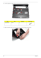
Main Unit Disassembly Process Main Unit Disassembly Flowchart Remove external modules before proceeding Remove keyboard Remove upper cover Remove LED Board Remove card reader board Remove main board Remove button board Remove Bluetooth board Remove LCD module Remove I/O board Remove Speakers Remove wifi switch board Remove thermal module Remove CRT Cable Remove DC cable Screw List Step Upper Cover Lower Cover HDD Bay Button Board LED Board Card Reader Board Bluetooth Board Mainboard Thermal Module I/O Board Wi-Fi Switch Board Speakers LCD Hinges Screw M2*10 M2*6 M2*3 M2*6 M2*3 M2*3 M2*3 M2*3 M2*3 M2*3 M2*3 M2*3 M2*3 M2*4 Quantity 6 8 2 1 2 1 2 1 2 4 2 1 2 4 Part No. 86.WHA02.004 86.WHA02.003 86.WHA02.001 86.WHA02.003 86.WHA02.001 86.WHA02.001 86.WHA02.001 86.WHA02.001 86.WHA02.001 86.WHA02.001 86.WHA02.001 86.WHA02.001 86.WHA02.001 86.WHA02.002 Chapter 3 51
-
 1
1 -
2
-
3
-
4
-
5
-
6
-
7
-
8
-
9
-
10
-
11
-
12
-
13
-
14
-
15
-
16
-
17
-
18
-
19
-
20
-
21
-
22
-
23
-
24
-
25
-
26
-
27
-
28
-
29
-
30
-
31
-
32
-
33
-
34
-
35
-
36
-
37
-
38
-
39
-
40
-
41
-
42
-
43
-
44
-
45
-
46
-
47
-
48
-
49
-
50
-
51
-
52
-
53
-
54
-
55
-
 56
56 -
 57
57 -
 58
58 -
 59
59 -
 60
60 -
 61
61 -
 62
62 -
 63
63 -
 64
64 -
 65
65 -
 66
66 -
67
-
68
-
69
-
70
-
71
-
72
-
73
-
74
-
75
-
76
-
77
-
78
-
79
-
80
-
81
-
82
-
83
-
84
-
85
-
86
-
87
-
88
-
89
-
90
-
91
-
92
-
93
-
94
-
95
-
96
-
97
-
98
-
99
-
100
-
101
-
102
-
103
-
104
-
105
-
106
-
107
-
108
-
109
-
110
-
111
-
112
-
113
-
114
-
115
-
116
-
117
-
118
-
119
-
120
-
121
-
122
-
123
-
124
-
125
-
126
-
127
-
128
-
129
-
130
-
131
-
132
-
133
-
134
-
135
-
136
-
137
-
138
-
139
-
140
-
141
-
142
-
143
-
144
-
145
-
146
-
147
-
148
-
149
-
150
-
151
-
152
-
153
-
154
-
155
-
156
-
157
-
158
-
159
-
160
-
161
-
162
-
163
-
164
-
165
-
166
-
167
-
168
-
169
-
170
-
171
-
172
-
173
-
174
-
175
-
176
-
177
-
178
-
179
-
180
-
181
-
182
 |
 |
