GE DSXH47EGWW Owners Manual - Page 13
Exhaust Direction, Gas Supply Requirements, Exhaust Ducting Length, Connecting The Dryer To, House
 |
UPC - 084691158943
View all GE DSXH47EGWW manuals
Add to My Manuals
Save this manual to your list of manuals |
Page 13 highlights
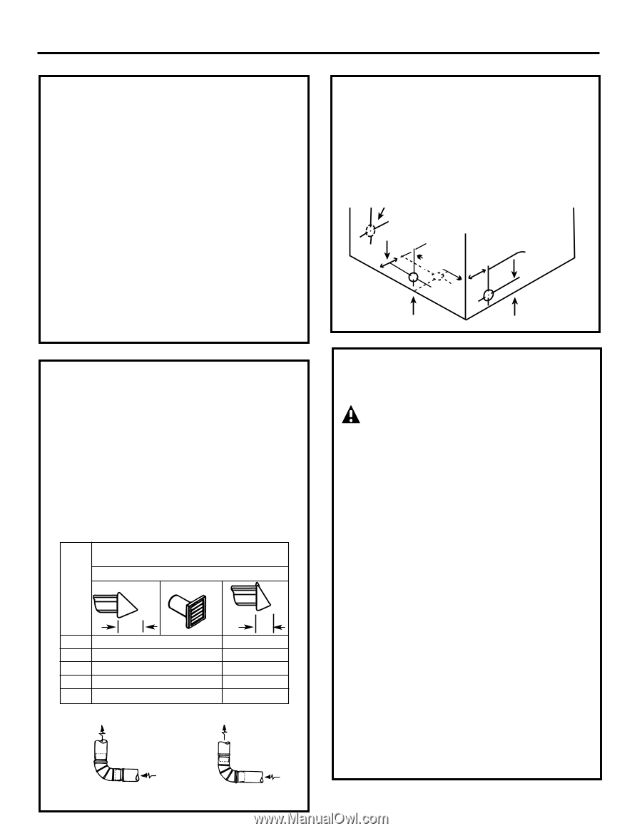
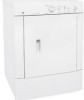
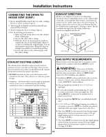
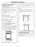
Installation Instructions CONNECTING THE DRYER TO HOUSE VENT (CONT.) • Never install flexible metal duct in walls, ceilings, floors or other enclosed spaces. • Total length of flexible metal duct should not exceed 8 feet (2.4 m). • Avoid resting the duct on sharp objects. • For best drying performance: 1. Slide one end of the duct over the clothes dryer outlet pipe. 2. Secure the duct with a clamp. 3. With the dryer in its permanent position, extend the duct to its full length. Allow 2″ of duct to overlap the exhaust pipe. Cut off and remove excess duct. Keep the duct as straight as possible for maximum airflow. 4. Secure the duct to the exhaust pipe with the other clamp. EXHAUST DIRECTION All dryers are shipped set up for rear exhausting. On electric dryers, exhausting can be on the cabinet right or left side, or through the dryer bottom. Gas dryers can exhaust on the cabinet right side or the dryer bottom. To change exhaust direction you will need Exhaust Kit Pub. No. 14-A018 and a rigid metal 4″ 90-degree elbow. The kit is available through your GE retailer. Follow the instructions supplied with the kit. Same as EXHAUST DUCT LOCATING other side DIMENSIONS 5 7/8″ (15 cm) 13 5/16″ (34 cm) 4 3/8″ (11 cm) 3 3/4″ (9.5 cm) 3 3/4″ (9.5 cm) EXHAUST DUCTING LENGTH The exhaust system should be inspected and cleaned a minimum of every year with normal usage. The more the dryer is used, the more often you should check the exhaust system and vent hood for proper operation. • DO NOT assemble the duct work with fasteners that extend into the duct. They will serve as collection points for lint. • Insulation - Ductwork which runs through an unheated area or is near an air conditioning duct should be insulated to reduce condensation and lint buildup. Number of 90° turns 0 1 2 3 4 MAXIMUM LENGTH of 4" (10.2 cm) Dia. RIGID METAL DUCT PREFERRED VENT HOOD TYPE 4" (10.2 cm) Louvered 4" (10.2 cm) 60' (18.28 m) 52' (15.84 m) 44' (13.41 m) 32' (9.75 m) 28' (8.53 m) 2.5" (6.35 cm) 48' (14.63 m) 40' (12.19 m) 32' (9.75 m) 24' (7.31 m) 16' (4.87 m) INSTALL MALE FITTINGS IN CORRECT DIRECTION CORRECT INCORRECT GAS SUPPLY REQUIREMENTS Replace brass connecting pipe that is not plastic-coated. Stainless steel or plastic-coated brass MUST be used. WARNING: Never reuse old flexible connectors. The use of old flexible connectors can cause gas leaks and personal injury. Always use NEW flexible connectors when installing a gas appliance. 1. Installation MUST conform with local codes, or in the absence of local codes, with the National Fuel Gas Code, ANSI Z223.1 (latest edition). 2. The gas supply line should be of 1/2″ (1.27 cm) rigid pipe. 3. If codes allow, flexible metal tubing may be used to connect your dryer to the gas supply line. The tubing MUST be constructed of stainless steel or plastic-coated brass. 4. The gas supply line MUST have an individual shutoff valve. 5. A 1/8″ (0.32 cm) NPT plugged tapping, accessible for test gauge connection, MUST be installed immediately upstream of the gas supply connection to the dryer. 6. The dryer MUST be disconnected from the gas supply piping system during any pressure testing of the gas supply piping system at test pressures in excess of 1/2 psig (3.45 kPa). 7. The dryer MUST be isolated from the gas supply piping system during any pressure testing of the gas supply piping system at test pressures equal to or less than 1/2 psig (3.45 kPa). 13
-
 1
1 -
2
-
3
-
4
-
5
-
6
-
7
-
 8
8 -
 9
9 -
 10
10 -
 11
11 -
 12
12 -
 13
13 -
 14
14 -
 15
15 -
 16
16 -
 17
17 -
 18
18 -
19
-
20
-
21
-
22
-
23
-
24
-
25
-
26
-
27
-
28
-
29
-
30
-
31
-
32
-
33
-
34
-
35
-
36
-
37
-
38
-
39
-
40
-
41
-
42
-
43
-
44
-
45
-
46
-
47
-
48
 |
 |