GE DSXH47EGWW Owners Manual - Page 17
Wire System For, Electric Dryers, Wire System
 |
UPC - 084691158943
View all GE DSXH47EGWW manuals
Add to My Manuals
Save this manual to your list of manuals |
Page 17 highlights
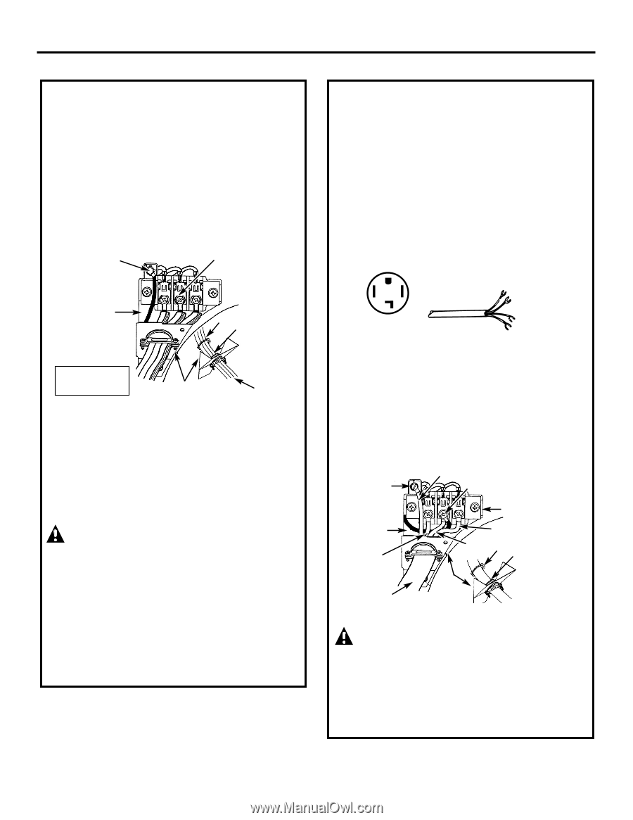
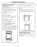
Installation Instructions 3-WIRE SYSTEM FOR ELECTRIC DRYERS DO NOT use for Mobile Home Installations. NOT for use on new construction. 1. Remove the screws securing the terminal block access cover and the strain relief mounting bracket located on the back of the dryer upper corner. 2. Install a UL-listed strain relief into the power cord entry hole of the mounting bracket. Finger-tighten the nut only at this time. Green ground screw Silver terminal Green neutral ground wire Nut Tighten nut to these threads Use copper conductors only. Strain relief mounting bracket Power cord 3. Thread a UL-listed 30A, 240V, 3 #10 AWG minimum copper conductor power cord through the strain relief. 4. Attach the power cord neutral (center wire) conductor to the silver-colored center terminal on the terminal block. Tighten the screw securely. 5. Attach the remaining two power cord outer conductors to the outer brass-colored terminals on the terminal block. Tighten both screws securely. WARNING: Do not make a sharp bend or crimp wiring/conductor at connections. 6. Reattach the strain relief mounting bracket to the back of the dryer with screws provided. Tighten screws securely. 7. Tighten the screws securing the cord restraint firmly against the power cord. 8. Tighten the strain relief nut securely so that the strain relief does not turn. 9. Reinstall the terminal block access cover. 4-WIRE SYSTEM FOR ELECTRIC DRYERS Effective January 1, 1996: The National Electrical Code requires that new construction (non existing) utilize a 4-wire connection to an electric dryer. 1. Remove the screws securing the terminal block access cover and the strain relief mounting bracket located on the back of the dryer upper corner. 2. Install a UL-listed strain relief in the entry hole of the mounting bracket. Finger-tighten the nut only at this time. 3. Remove the green neutral ground wire from the green ground screw located above the terminal block. Typical 4 conductor receptacle Typical 4 conductor cord Black 240V White neutral Red 240V Green ground 4. Thread a UL-listed 30A, 240V, 4 #10 AWG minimum copper conductor power cord through the strain relief. 5. Attach the green power cord ground wire to the cabinet with the green ground screw. 6. Attach the white (neutral) power cord conductor from the power cord and the green ground wire from the dryer harness to the silver-colored center terminal on the terminal block. Tighten the screw securely. 7. Attach the red and black power cord conductors to the outer brass-colored terminals on the terminal block. Green ground screw Green power cord ground wire Silver terminal Green neutral ground wire Red Terminal block Black White Nut Tighten nut to these threads Power cord Strain relief mounting bracket WARNING: Do not make a sharp bend or crimp wiring/conductor at the connections. 8. Tighten the screws securing the cord restraint firmly against the power cord. 9. Tighten the strain relief nut securely so the strain relief does not turn. 10. Reinstall the terminal block access cover. 17
-
 1
1 -
2
-
3
-
4
-
5
-
6
-
7
-
8
-
9
-
10
-
11
-
 12
12 -
 13
13 -
 14
14 -
 15
15 -
 16
16 -
 17
17 -
 18
18 -
 19
19 -
 20
20 -
 21
21 -
 22
22 -
23
-
24
-
25
-
26
-
27
-
28
-
29
-
30
-
31
-
32
-
33
-
34
-
35
-
36
-
37
-
38
-
39
-
40
-
41
-
42
-
43
-
44
-
45
-
46
-
47
-
48
 |
 |