GE JGP990WELWW Owners Manual - Page 23
Prepare For Ductwork, Blower To Ductwork, Alignment
 |
View all GE JGP990WELWW manuals
Add to My Manuals
Save this manual to your list of manuals |
Page 23 highlights
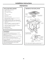
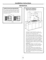
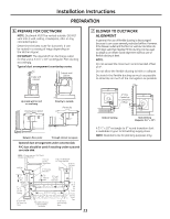
Installation Instructions PREPARATION 6 PREPARE FOR DUCTWORK NOTE: Ductwork MUST be vented outside. DO NOT vent into a wall, ceiling, crawlspace, attic or any concealed space. Determine the best route for ductwork; it can be routed in a variety of ways depending on the kitchen layout. IMPORTANT: The downdraft air discharge outlet for this unit is 3-1/4″ x 10″ rectangular. Plan ducting accordingly. Typical duct arrangement countertop series. Inside wall cabinet Outside wall cabinet 7 BLOWER TO DUCTWORK ALIGNMENT In general, the use of flexible ducting is discouraged because it can cause severely restricted airflow. However, if the blower outlet and the floor or wall duct location do NOT align well, then flexible METAL ducting can be used to adapt to an offset. Good alignment without use of flexible ducting is best. NOTE: Do not exceed the maximum recommended offset of 6″. Do not allow the flexible ducting to kink or collapse. Do stretch the flexible ducting as much as possible to eliminate as much of the corrugation as possible. Up inside wall to roof or overhang Peninsula or island Directly to outside Peninsula Between floor joists Through cabinet toe space Optional duct arrangement under concrete slab. PVC duct should be used if installing under a poured concrete slab. NOTE: PVC sewer pipe type PSM 12454-B Schedule 40 ASTM D1785. 6″ (15 cm) Dia. 90° Metal Elbow Wall Cap 6″ (15 cm) Dia. Metal Duct 3-1/4″ x 10″ Rectangular to 6″ Round Transition Concrete Slab 6″ (15 cm) Dia. Metal Duct 12″ (30 cm) Min. 6″ (15 cm) Dia. PVC Coupling 6″ (15 cm) Dia. PVC Sewer Pipe Elbow 16″ (40.6 cm) Max. 6″ (15 cm) Dia. PVC Sewer Pipe 30′-0″ (9.14 m) Max. Pack tightly with gravel or sand completely around pipe 6″ (15 cm) Dia. PVC Sewer Pipe Elbow 6″ (15 cm) Dia. PVC Coupling 6″ (15 cm) Dia. PVC Sewer Pipe 23 6″ Max. Centerline to Centerline Offset Bottom Venting Back Venting (Requires 31/4″ x 10″) A 31⁄4″ x 10″ rectangle to 6″ round transition duct is available at your local building supply store. NOTE: Illustrations are for planning purposes only.
-
 1
1 -
2
-
3
-
4
-
5
-
6
-
7
-
8
-
9
-
10
-
11
-
12
-
13
-
14
-
15
-
16
-
17
-
 18
18 -
 19
19 -
 20
20 -
 21
21 -
 22
22 -
 23
23 -
 24
24 -
 25
25 -
 26
26 -
 27
27 -
 28
28 -
29
-
30
-
31
-
32
-
33
-
34
-
35
-
36
-
37
-
38
-
39
-
40
-
41
-
42
-
43
-
44
-
45
-
46
-
47
-
48
-
49
-
50
-
51
-
52
-
53
-
54
-
55
-
56
-
57
-
58
-
59
-
60
-
61
-
62
-
63
-
64
-
65
-
66
-
67
-
68
-
69
-
70
-
71
-
72
-
73
-
74
-
75
-
76
-
77
-
78
-
79
-
80
 |
 |
