GE PSB48YSXSS Use and Care Manual - Page 17
THE INSTALLATION SPACE, DIMENSIONS AND CLEARANCES, Water and Electrical Locations - 48
 |
UPC - 084691175933
View all GE PSB48YSXSS manuals
Add to My Manuals
Save this manual to your list of manuals |
Page 17 highlights
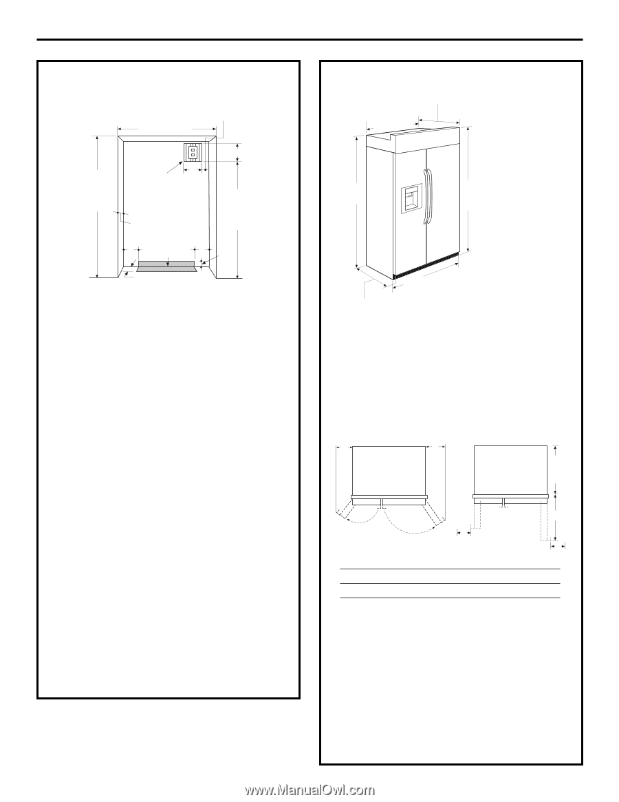
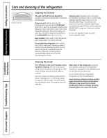
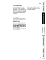
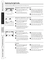
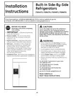
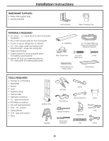
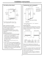
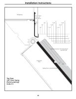
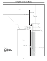
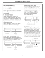
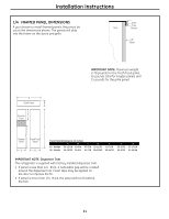
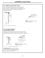
Installation Instructions THE INSTALLATION SPACE *Finished Width 84 1/2" max Electrical 7" 83 1/2" min Area Finished Opening 24" 3" 7" 74" From Floor to Bottom of Electrical DIMENSIONS AND CLEARANCES 25-3/8" Case Depth *Shipping height **Case Width The front height may be adjusted from 83-1/2″ to 84-1/2″ by adjusting front and rear leveling legs a maximum of 1″. *81-3/4" at Rear *84" From Floor to Top Frame 5" Water Supply 5" 3 1/2" 3 1/2" *The finished cutout width must be: 41-1/2″ for 42″ models and 47-1/2″ for 48″ models Water and Electrical Locations The opening must be prepared with the electrical and water supply located as shown. The cutout depth must be 24″ The refrigerator will project forward, slightly beyond adjacent cabinets, depending on your installation. Additional Specifications • A 120 volt, 60Hz, 15 or 20 amp power supply is required. An individual properly grounded branch circuit or circuit breaker is recommended. Install a properly grounded 3-prong electrical receptacle recessed into the back wall. Electrical must be located on rear wall as shown. Note: GFI (ground fault interrupter) is not recommended. • Water line can enter the opening through the floor or rear wall. The water line installed should be 1/4″ O.D. copper tubing or GE SmartConnect™ tubing between the cold water line and water connection location. The line should be long enough to extend to the front of the refrigerator. Installation of an easily accessible shutoff valve in the water line is required. 42" Frame-to-Frame for 42" Models 48" Frame-to-Frame for 48" Models Depth Including Handles 26-7/8" **The case width must be: 41″ for 42″ models and 47″ for 48″ models Product Clearances These refrigerators are equipped with a 2 position door stop. The factory set 130° door swing can be adjusted to 90° if clearance to adjacent cabinets or walls is restricted. 130° Door Swing 90° Door Swing A B 23-7/8" Behind Frame D Models A B C 42″ 12-3/16″ 16″ 24″ 48″ 13-7/16″ 18-9/16″ 28″ C D D 5″ 5″ Allow minimum clearances for Freezer door (Dimension A) and Fresh Food door (Dimension B) for a full 130° door swing and to allow for drawer removal. Four inch (4″) minimum clearance is required when door swing is adjusted to 90°. If the 90° door stop position is used, drawer access is maintained, but drawer removal is restricted. See illustrations, pages 18 and 19, to determine door swing interaction with adjacent cabinets or countertops. 17
-
 1
1 -
2
-
3
-
4
-
5
-
6
-
7
-
8
-
9
-
10
-
11
-
 12
12 -
 13
13 -
 14
14 -
 15
15 -
 16
16 -
 17
17 -
 18
18 -
 19
19 -
 20
20 -
 21
21 -
 22
22 -
23
-
24
-
25
-
26
-
27
-
28
-
29
-
30
-
31
-
32
-
33
-
34
-
35
-
36
-
37
-
38
-
39
-
40
-
41
-
42
-
43
-
44
-
45
-
46
-
47
-
48
-
49
-
50
-
51
-
52
-
53
-
54
-
55
-
56
-
57
-
58
-
59
-
60
-
61
-
62
-
63
-
64
-
65
-
66
-
67
-
68
-
69
-
70
-
71
-
72
-
73
-
74
-
75
-
76
-
77
-
78
-
79
-
80
-
81
-
82
-
83
-
84
-
85
-
86
-
87
-
88
-
89
-
90
-
91
-
92
-
93
-
94
-
95
-
96
-
97
-
98
-
99
-
100
 |
 |