Gigabyte GA-6UASL1 Manual - Page 20
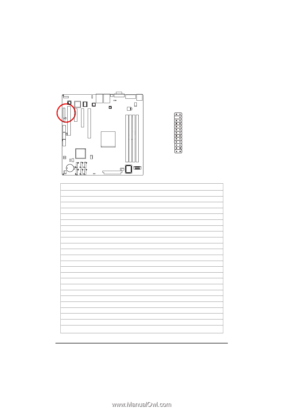
F_PANEL, 2X12 Pins Front Panel connector
 |
View all Gigabyte GA-6UASL1 manuals
Add to My Manuals
Save this manual to your list of manuals |
Page 20 highlights
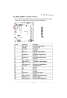
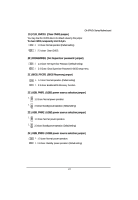
6 ) F_PANEL (2X12 Pins Front Panel connector) GA-6FASV Series Motherboard Please connect the power LED, PC speaker, reset switch and power switch of your chassis front panel to the F_PANEL connector according to the pin assignment above. 12 23 24 Pin No. 1. 2. 3. 4. 5. 6. 7. 8. 9. 10. 11. 12. 13. 14. 15. 16. 17. 18. 19. 20. 21. 22. 23. 24. Signal Name Power LED + 5V standby Pin removed NC Power LED NC HD status LED+ NC HD status LEDNC Power on switch LAN1 active LED (-) GND LAN1 active LED (+) Reset switch NC GND NC NC CASEOPEN NC LAN2 active LED (-) NMI switch LAN2 active LED (+) Description Power LED Signal anode (+) Front panel power Pin removed No connect Power LED Signal cathode(-) No connect Hard Disk LED Signal anode (+) No connect Hard Disk LED Signal cathode(-) No connect Power button LAN1 active LED Signal cathode(-) Ground LAN1 active LED Signal anode (+) Reset button Signal No connect Ground No connect No connect Chassis intrusion Signal No connect LAN2 active LED Signal cathode(-) NMI switch Signal LAN2 active LED Signal anode (+) 20
-
 1
1 -
2
-
3
-
4
-
5
-
6
-
7
-
8
-
9
-
10
-
11
-
12
-
13
-
14
-
 15
15 -
 16
16 -
 17
17 -
 18
18 -
 19
19 -
 20
20 -
 21
21 -
 22
22 -
 23
23 -
 24
24 -
 25
25 -
26
-
27
-
28
-
29
-
30
-
31
-
32
-
33
-
34
-
35
-
36
-
37
-
38
-
39
-
40
-
41
-
42
-
43
-
44
-
45
-
46
-
47
-
48
-
49
-
50
-
51
-
52
-
53
-
54
-
55
-
56
-
57
-
58
-
59
-
60
-
61
 |
 |