Gigabyte GA-6UASL1 Manual - Page 22
/16/17 FAN1/2/3/4 CPU fan/System fan cable connectors, AUDIO Front AUDIO connector/Option
 |
View all Gigabyte GA-6UASL1 manuals
Add to My Manuals
Save this manual to your list of manuals |
Page 22 highlights
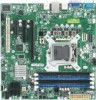
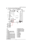
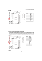
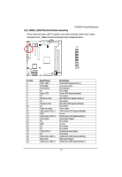
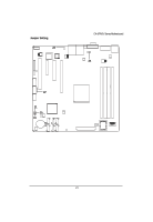
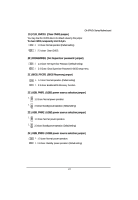
GA-6FASV Series Motherboard 14/15/16/17 ) FAN1/2/3/4 (CPU fan/System fan cable connectors) The cooler fan power connector supplies a +12V power voltage via a 3-pin/4-pin(CPU_FAN) power connector and possesses a foolproof connection design. Most coolers are designed with color-coded power connector wires. A red power connector wire indicates a positive connection and requires a +12V power voltage. The black connector wire is the ground wire (GND). Remember to connect the CPU/system fan cable to the CPU_FAN/SYS_FAN connector to prevent CPU damage or system hanging caused by overheating. 1 FAN2 FAN1 FAN3 1 Pin No. 1 2 3 4 Definition GND 12V Sense Control FAN4 18 )AUDIO (Front AUDIO connector/Option) In order to utilize the front audio header, your chassis must have front audio connector. Also please make sure the pin assignment on the cable is the same as the pin assignment on the MB header. To find out if the chassis you are buying support front audio connector, please contact your dealer. 2 12 1 11 Pin No. 1 2 3 4 5 6 7 8 9 10 11 12 Definition Line IN (R) MIC (R) Line IN (L) MIC (L) Line IN Jack Detect GND GND Line Out Jack Detect Line Out (R) MIC Jack Detect Line Out (L) Key 22
-
 1
1 -
2
-
3
-
4
-
5
-
6
-
7
-
8
-
9
-
10
-
11
-
12
-
13
-
14
-
15
-
16
-
 17
17 -
 18
18 -
 19
19 -
 20
20 -
 21
21 -
 22
22 -
 23
23 -
 24
24 -
 25
25 -
 26
26 -
 27
27 -
28
-
29
-
30
-
31
-
32
-
33
-
34
-
35
-
36
-
37
-
38
-
39
-
40
-
41
-
42
-
43
-
44
-
45
-
46
-
47
-
48
-
49
-
50
-
51
-
52
-
53
-
54
-
55
-
56
-
57
-
58
-
59
-
60
-
61
 |
 |