Gigabyte GA-965P-DS3 Manual - Page 20
Connectors Introduction - s3 motherboard
 |
View all Gigabyte GA-965P-DS3 manuals
Add to My Manuals
Save this manual to your list of manuals |
Page 20 highlights
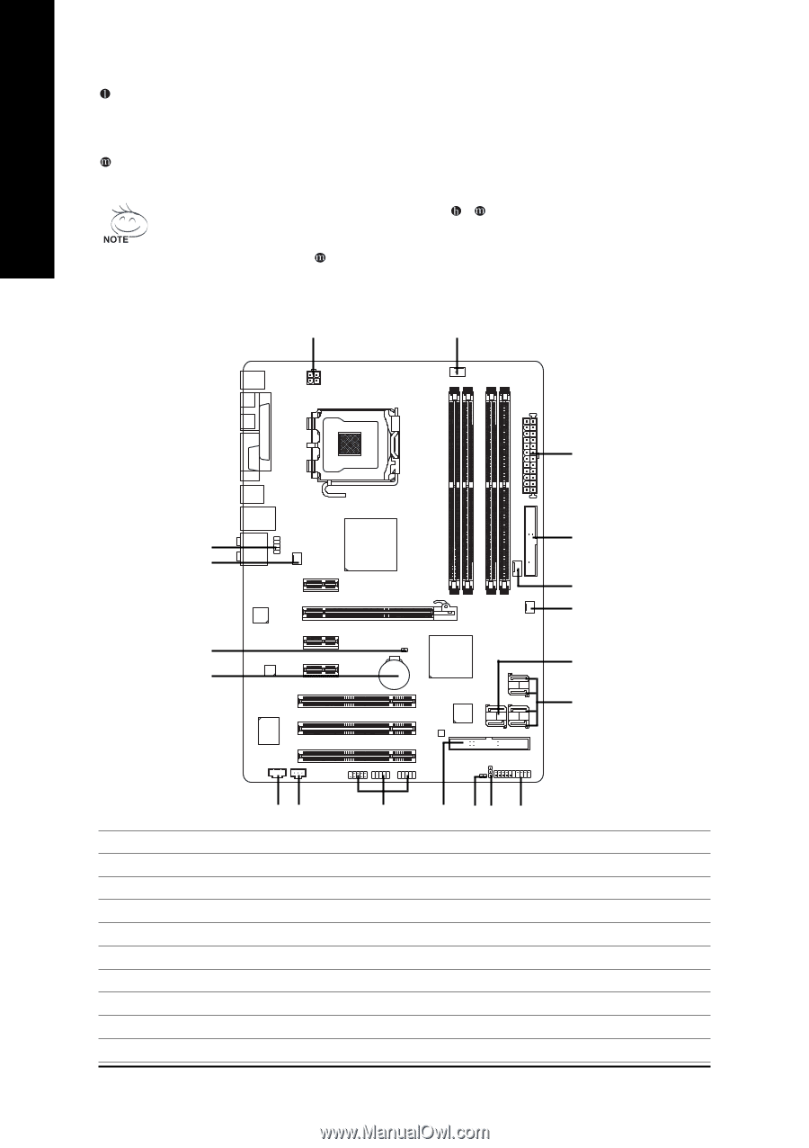
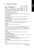
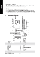
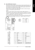
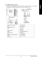
English Line Out (Front Speaker Out) The default Line Out (Front Speaker Out) jack. Stereo speakers, earphone or front surround speakers can be connected to Line Out (Front Speaker Out) jack. MIC In The default MIC In jack. Microphone must be connected to MIC In jack. In addition to the default speakers settings, the ~ audio jacks can be reconfigured to perform different functions via the audio software. Only microphones still MUST be connected to the default Mic In jack ( ) . Please refer to the 2-/4-/6-/8- channel audio setup steps for detailed software configuration information. 1-7 Connectors Introduction 1 3 2 12 7 6 4 5 18 10 19 9 14 15 1) ATX_12V 2) ATX (Power Connector) 3) CPU_FAN 4) SYS_FAN 5) PWR_FAN 6) NB_FAN 7) FDD 8) IDE1 9) SATAII0/1/2/3 10) GSATAII0/1 GA-965P-DS3/S3 Motherboard 16 8 17 13 11 11) F_PANEL 12) F_AUDIO 13) PWR_LED 14) CD_IN 15) SPDIF_I 16) F_USB1/F_USB2/F_USB3 17) CI 18) CLR_CMOS 19) BATTERY - 20 -
-
 1
1 -
2
-
3
-
4
-
5
-
6
-
7
-
8
-
9
-
10
-
11
-
12
-
13
-
14
-
 15
15 -
 16
16 -
 17
17 -
 18
18 -
 19
19 -
 20
20 -
 21
21 -
 22
22 -
 23
23 -
 24
24 -
 25
25 -
26
-
27
-
28
-
29
-
30
-
31
-
32
-
33
-
34
-
35
-
36
-
37
-
38
-
39
-
40
-
41
-
42
-
43
-
44
-
45
-
46
-
47
-
48
-
49
-
50
-
51
-
52
-
53
-
54
-
55
-
56
-
57
-
58
-
59
-
60
-
61
-
62
-
63
-
64
-
65
-
66
-
67
-
68
-
69
-
70
-
71
-
72
-
73
-
74
-
75
-
76
-
77
-
78
-
79
-
80
-
81
-
82
-
83
-
84
-
85
-
86
-
87
-
88
 |
 |