Gigabyte GA-965P-DS3 Manual - Page 22
CPU_FAN / SYS_FAN / PWR_FAN Cooler Fan Power Connector, NB_FAN Chip Fan Power Connector
 |
View all Gigabyte GA-965P-DS3 manuals
Add to My Manuals
Save this manual to your list of manuals |
Page 22 highlights
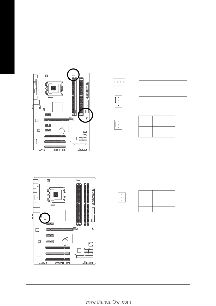
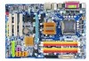
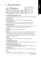
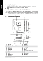
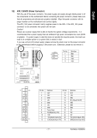
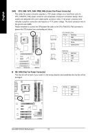
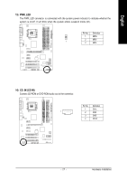
English 3/4/5) CPU_FAN / SYS_FAN / PWR_FAN (Cooler Fan Power Connector) The cooler fan power connector supplies a +12V power voltage via a 3-pin/4-pin (only for CPU_FAN/SYS_FAN) power connector and possesses a foolproof connection design. Most coolers are designed with color-coded power connector wires. A red power connector wire indicates a positive connection and requires a +12V power voltage. The black connector wire is the ground wire (GND). Please remember to connect the CPU/system fan cable to the CPU_FAN/SYS_FAN connector to prevent the CPU/system from overheating and failure. 1 CPU_FAN 1 CPU_FAN/SYS_FAN: Pin No. Definition 1 GND 2 +12V/Speed Control 3 Sense 4 Speed Control SYS_FAN 1 PWR_FAN PWR_FAN: Pin No. 1 2 3 Definition GND +12V NC 6) NB_FAN (Chip Fan Power Connector) The chip fan will not work if you install it in the wrong direction and sometimes the chip fan will be damaged. 1 Pin No. Definition 1 GND 2 +12V 3 NC GA-965P-DS3/S3 Motherboard - 22 -
-
 1
1 -
2
-
3
-
4
-
5
-
6
-
7
-
8
-
9
-
10
-
11
-
12
-
13
-
14
-
15
-
16
-
 17
17 -
 18
18 -
 19
19 -
 20
20 -
 21
21 -
 22
22 -
 23
23 -
 24
24 -
 25
25 -
 26
26 -
 27
27 -
28
-
29
-
30
-
31
-
32
-
33
-
34
-
35
-
36
-
37
-
38
-
39
-
40
-
41
-
42
-
43
-
44
-
45
-
46
-
47
-
48
-
49
-
50
-
51
-
52
-
53
-
54
-
55
-
56
-
57
-
58
-
59
-
60
-
61
-
62
-
63
-
64
-
65
-
66
-
67
-
68
-
69
-
70
-
71
-
72
-
73
-
74
-
75
-
76
-
77
-
78
-
79
-
80
-
81
-
82
-
83
-
84
-
85
-
86
-
87
-
88
 |
 |