Gigabyte GA-Z170X-Gaming GT User Manual - Page 23
Onboard Buttons and Switches, BIOS Switches and BIOS LED Indicators, Audio Gain Control Switches
 |
View all Gigabyte GA-Z170X-Gaming GT manuals
Add to My Manuals
Save this manual to your list of manuals |
Page 23 highlights
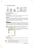
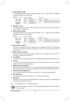
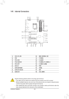
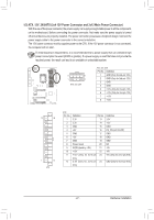
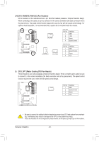
_ __ 3 _S B S_ B B S_ B S_ S_ _ _B U __ 3 _S S 1 1 S 1 23 _S _S S S S3 S_ S_ 1-8 Onboard Buttons and Switches 1 23 1 23 1 23 BIO1S2 3Switches and BIOS LED Indicators _ 1 1 23 The BIOS switch (BIOS_SW) allows users to easily select a different BIOS for boot up or overclocking, helping to _ reduce BIOS failure during overclocking. The SB switch allows enabling or disabling of the Dual BIOS function. The LED indicator (MBIOS_LED/BBIOS_LED) shows which BIOS is active. S3 F_USB3 F B _U __ F_USB3 F S_ _ B B _U S _U _S S B_ S_B _ B 1 23 B _B S B_ _ B S 1 23 1 B_ BIOS_SW 1 23 S _ S 2 1 1: Main BIOS (Boot from the main BIOS) B SS S SF SF 2 1 2: Backup BIOS (Boot from the backup BIOS) B SS S B_ B_ S _ _B _ _B B SS S SB 2 1 1: Dual BIOS S 3 _ _ B S 3S S SF __ 3 SF 2 1 2: Single BIOS 1 23 _ _ B_ 1 23 BIOS LED Indicators: U MBIOS_LED BIOS_SW SB BBIOS_LED MBIOS_LED (The main BIOS is active) BBIOS_LED (The backup BIOS is active) 1 23 _ 1 23 1 23 1 23 _ 1 23 _ S_ S_ _U B SS S 1 1 23 S 1 23 U S3 U __ 3 1 1 23 1 23 1 23 1 23 1 _ _ 1 Au1 dio Gain Control Switches 1 23 The switches allow for audio gain control for the line-out jack on the back panel. Please make sure all of the _ _B dips are set in the same position and are set according to your headphone specification (actual effects may vary by the device being used). S_ S_ __ 3 _ _B SF B SS S CAP_SW_F (Front audio line out) 1 2 CAP_SW_R (Headphone out) SF 1 2 F_USB3 F S_ _ B _U _ B 1: 2.5x (Default) 2: 6x B_ B_ S B_ B _S B_ S S B SS S S B_ F_USB3 F B _S S_ _ B _U _ B CAP_SW_R CAP_SW_F 1 23 1 _ B _ B S3 S3 S_ S_ S_ S_ B S_ B - 23 - Hardware Installation B S_ B F _0 _F _0 F
-
 1
1 -
2
-
3
-
4
-
5
-
6
-
7
-
8
-
9
-
10
-
11
-
12
-
13
-
14
-
15
-
16
-
17
-
 18
18 -
 19
19 -
 20
20 -
 21
21 -
 22
22 -
 23
23 -
 24
24 -
 25
25 -
 26
26 -
 27
27 -
 28
28 -
29
-
30
-
31
-
32
-
33
-
34
-
35
-
36
-
37
-
38
-
39
-
40
-
41
-
42
-
43
-
44
-
45
-
46
-
47
-
48
-
49
-
50
-
51
-
52
-
53
-
54
-
55
-
56
-
57
-
58
-
59
-
60
-
61
-
62
-
63
-
64
-
65
-
66
-
67
-
68
-
69
-
70
-
71
-
72
-
73
-
74
-
75
-
76
-
77
-
78
-
79
-
80
-
81
-
82
-
83
-
84
-
85
-
86
-
87
-
88
-
89
-
90
-
91
-
92
-
93
-
94
-
95
-
96
-
97
-
98
-
99
-
100
-
101
-
102
-
103
-
104
-
105
-
106
-
107
-
108
-
109
-
110
-
111
-
112
-
113
-
114
-
115
-
116
-
117
-
118
-
119
-
120
-
121
-
122
-
123
-
124
-
125
-
126
-
127
-
128
-
129
-
130
-
131
-
132
 |
 |
