Gigabyte GA-Z170X-Gaming GT User Manual - Page 25
Changing the Operational Amplifier
 |
View all Gigabyte GA-Z170X-Gaming GT manuals
Add to My Manuals
Save this manual to your list of manuals |
Page 25 highlights
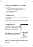
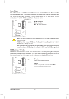
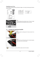
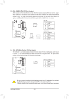
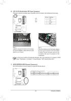
SSSSSSSS 1 231 231 231 231 231 231 231 23 1 23 1 23 1 23 1 23 1 23 1 23 1 23 1 23 1 23 1 23 1 23 1 23 1 23 1 23 1 23 1 23 SSSSSSSS 1 231 231 231 231 231 231 231 23 Voltage Measurement Points Use a multimeter to measure the following motherboard voltages. You can employ the following way to measure component voltages. VPP_25V VDIMM PCHIO DDRVTT VCORE VAXG VCCIO S S3 VSA S3 S3 S3 S3 S3 S3 Pi3nB SNBSoS. BS SSDBSeSSfiBSnSiStBiSonSSBS SSBS SS S S S U U U U U U UU _ __ __3 __3 __3 __3 1 Power 2 GND Pin 1 Pin 1 Pin 1 Pin 1 Pin 1 Pin 1 Pin 1 Pin 1 S S_ S_ S_ S_ S_ S_ S_ _ S FS FS FS FS FS FS FS F ________ B_ B_ B_ B_ B_ B_ B_ B_ ________ Steps: Connect the red lead of the multimeter to the pin 1 (Power) of a voltage measurement point and the black lead to the pin 2 (ground). S S_ S_ S_ S_ S_ S_ S_ _ _ __B __B 1-9 Changing the Operational Amplifier SteSp 1S_: S_ S_ S_ S_ S_ S_ _ Use an IC extractor to carefully grip the IC's sides and extract it from the socket. Step 2: U U U U U U B_U B_U B_ B_ B_ B_ B_ B_ Align the notch on your OP chip with the notch on the socket and gently press the chip into the socket until seated. For purchasing the IC extractor and OP Chip, please contact the local dealer. - 25 - Hardware Installation
-
 1
1 -
2
-
3
-
4
-
5
-
6
-
7
-
8
-
9
-
10
-
11
-
12
-
13
-
14
-
15
-
16
-
17
-
18
-
19
-
 20
20 -
 21
21 -
 22
22 -
 23
23 -
 24
24 -
 25
25 -
 26
26 -
 27
27 -
 28
28 -
 29
29 -
 30
30 -
31
-
32
-
33
-
34
-
35
-
36
-
37
-
38
-
39
-
40
-
41
-
42
-
43
-
44
-
45
-
46
-
47
-
48
-
49
-
50
-
51
-
52
-
53
-
54
-
55
-
56
-
57
-
58
-
59
-
60
-
61
-
62
-
63
-
64
-
65
-
66
-
67
-
68
-
69
-
70
-
71
-
72
-
73
-
74
-
75
-
76
-
77
-
78
-
79
-
80
-
81
-
82
-
83
-
84
-
85
-
86
-
87
-
88
-
89
-
90
-
91
-
92
-
93
-
94
-
95
-
96
-
97
-
98
-
99
-
100
-
101
-
102
-
103
-
104
-
105
-
106
-
107
-
108
-
109
-
110
-
111
-
112
-
113
-
114
-
115
-
116
-
117
-
118
-
119
-
120
-
121
-
122
-
123
-
124
-
125
-
126
-
127
-
128
-
129
-
130
-
131
-
132
 |
 |
