Gigabyte GA-Z270X-DESIGNARE Users Manual - Page 16
SYS_FAN3_PUMP System Fan/Water Cooling Pump Header, CPU_OPT Water Cooling CPU Fan Header
 |
View all Gigabyte GA-Z270X-DESIGNARE manuals
Add to My Manuals
Save this manual to your list of manuals |
Page 16 highlights
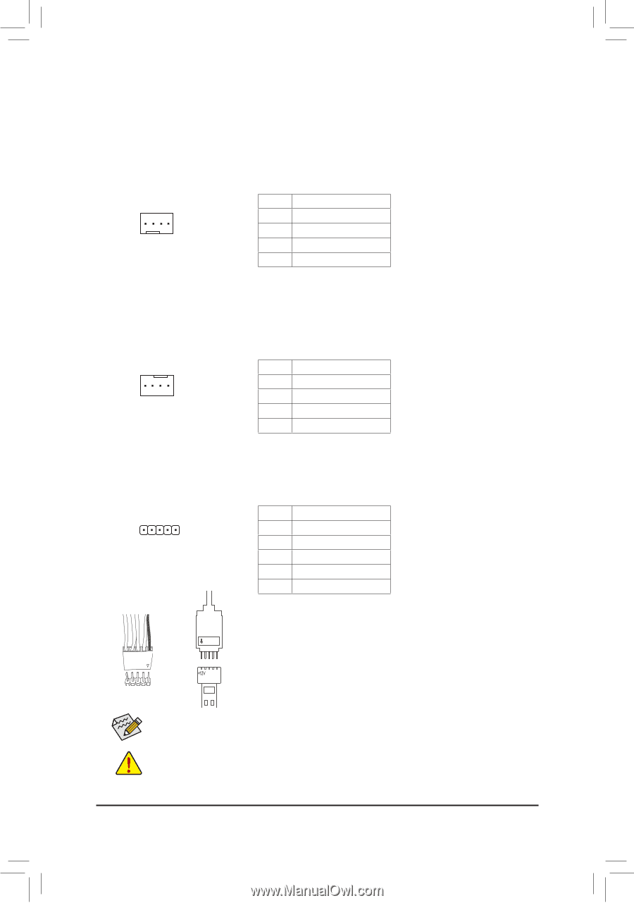
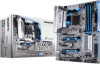
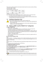
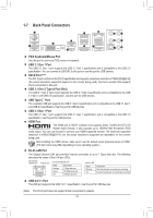
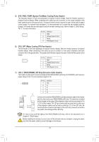
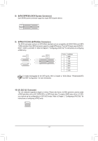
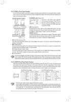
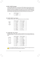
1 1 23 1 23 S B_ B S _S 5) SYS_FAN3_PUMP (System Fan/Water Cooling _PuSmp Header) The fan/pump header is 4-pin and possesses a foolproof insertion design. Most fan headers possess a foolproof insertion design. When connecting a fan cable, Sb__e sure to connect it in the correct orientation (the black connector wire is the ground wire). The speed controlBfunction requires the use of a fan with fan speed control design. For optimum heat dissipation, it is recommended that a system fan be installed inside the chassis. The header also provides speed control for a water cooling pump, refer to Chapter 2, "BIOS Setup," U "M.I.T.," for more information __ 3 _U _ Pin No. Definition B 1 GND 1 2 Voltage Speed Control 3 Sense F_USB3 F 4 PWM Speed Control _ 6) CPU_OPT (Water Cooling CPU Fan Header) The fan header is 4-pin and possesses a foolproof insertion design. Most fan headers possess a foolproof insertion design. When con_nec_tBing a fan cable, be sure to connect it in the correct orientation (the black connector wire is the ground wire). The speed control function requires the use of a fan with fan speed control design. _ Pin No. Definition 1 1 GND 2 Voltage Speed Control 3 Sense 4 PWM Speed Control 7) LED_C (RGB (RGBW) LED Strip Extension Cable Header) The header can be used to connect a standard 5050 RGB (RGBW) LED strip (12V/G/R/B/W), with maximum power rating of 2A (12V) and maximum length of 2m. _ 1 Pin No. 1 2 3 4 5 Definition 12V G R B W Black wire 12V of the 1 LED strip 12V Connect one end of the RGB (RGBW) LED strip extension cable to the header and the other end to your RGB (RGBW) LED strip. The black wire (marked with a triangle on the plug) of the extension cable must be connected to Pin 1 (12V) of this header. The 12V pin (marked with an arrow) on the other end of the extension cable must be lined up with the 12V of the LED strip. Be careful with the connection orientation of the LED strip; incorrect connection may lead to the damage of the LED strip. USB 0_ B For how to turn on/off the lights of the RGB (RGBW) LED strip, refer to the instructions on in Chapter 2, "BIOS Setup." B_ Before installinFg_UthSeB3devices, be sure to turn off the devices and your computer. Unplug the power cord from the power outlet to prevent damage to the devices. - 16 - F _0 _F _0 F
-
 1
1 -
2
-
3
-
4
-
5
-
6
-
7
-
8
-
9
-
10
-
 11
11 -
 12
12 -
 13
13 -
 14
14 -
 15
15 -
 16
16 -
 17
17 -
 18
18 -
 19
19 -
 20
20 -
 21
21 -
22
-
23
-
24
-
25
-
26
-
27
-
28
-
29
-
30
-
31
-
32
-
33
-
34
-
35
-
36
-
37
-
38
-
39
-
40
-
41
-
42
-
43
-
44
-
45
-
46
-
47
-
48
 |
 |