Gigabyte GA-Z270X-DESIGNARE Users Manual - Page 21
TPM Trusted Platform Module Header, CLR_CMOS Clear CMOS Jumper, F_USB1/F_USB2 USB 2.0/1.1 Headers
 |
View all Gigabyte GA-Z270X-DESIGNARE manuals
Add to My Manuals
Save this manual to your list of manuals |
Page 21 highlights
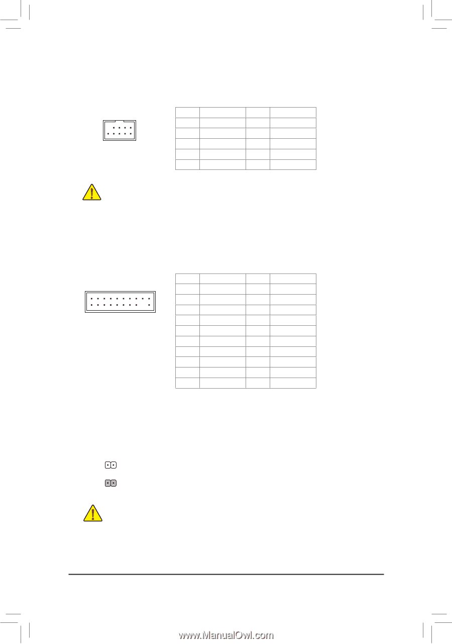
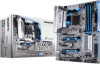
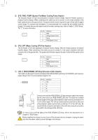
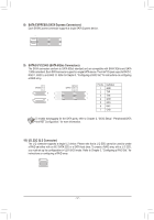
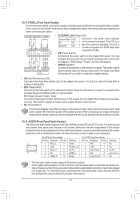
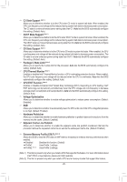
17) F_USB1/F_USB2 (USB 2.0/1.1 Headers) The headers conform to USB 2.0/1.1 specification. Each USB header can provide two USB ports via an optional USB bracket. For purchasing the optional USB bracket, please contact the local dealer. Pin No. Definition Pin No. Definition F_USB30 9 10 1 2 1 Power (5V) F2_ U Power (5V) 6 USB DY+ 7 GND F_ 3 USB DX- 8 GND 4 USB DY- 9 No Pin 5 USB DX+ 10 NC •• Do not plug the IEEE 1394 bracket (2x5-pin) cable into the USB 2.0/1.1 header. •• Prior to installing the USB bracket, be sure to turn off your computer and unplug the power cord from the power outlet to prevent damage to the USB bracket. 1 23 1 B SS B_ 18) TPM (Trusted Platform Module Header) 1 You may connect a TPM (Trusted Platform Module) to this header. _S 1 23 1 1 23 1 Pin No. Definition Pin No. Definition 19 1 1 LCLK 11 LAD0 2 GND 12 GND S 3 LFRAME 13 NC 20 2 4 No Pin 14 NC 5 LRESET 6 NC 7 LAD3S 15 SB3V 1 23 16 SERIRQ 17 GND 8 LAD2 18 NC 9 VCC3 19 NC 10 LAD1 20 NC 19) CLR_CMOS (Clear CMOS Jumper) Use this jumper to clear the BIOS configuration and reset the CMOS values to factory defaults. To clear the CMOS values, use a metal object like a screwdriver to touch the two pins for a few seconds. S3 B SS S U __ 3 Open: Normal Short: Clear CMOS Values S _ •• Always turn off your computer and unplugS thFe power cord from the power outlet before clearing the CMOS values. _ •• After system restart, go to BIOS Setup to load factory defaults (select Load Optimized Defaults) or manually configure the BIOS settings (refer to Chapter 2, "BIOS Setup," for BIOS configurations). _ _B B_ - 21 - S _S _ S_
-
 1
1 -
2
-
3
-
4
-
5
-
6
-
7
-
8
-
9
-
10
-
11
-
12
-
13
-
14
-
15
-
 16
16 -
 17
17 -
 18
18 -
 19
19 -
 20
20 -
 21
21 -
 22
22 -
 23
23 -
 24
24 -
 25
25 -
 26
26 -
27
-
28
-
29
-
30
-
31
-
32
-
33
-
34
-
35
-
36
-
37
-
38
-
39
-
40
-
41
-
42
-
43
-
44
-
45
-
46
-
47
-
48
 |
 |