Gigabyte GA-Z270X-DESIGNARE Users Manual - Page 17
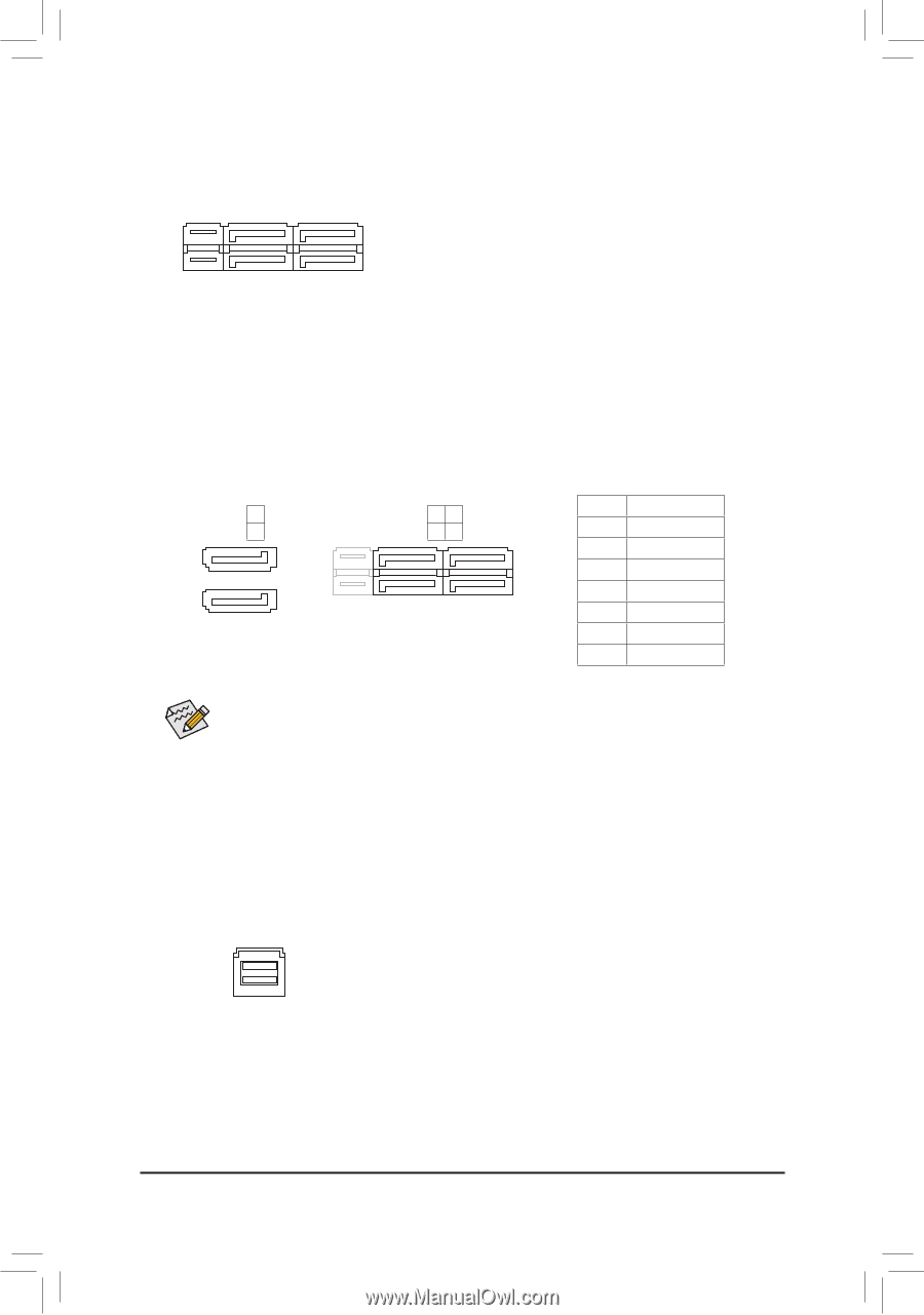
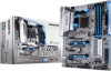
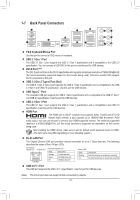
SATA3 0/1/2/3/4/5 SATA 6Gb/s Connectors, SATA EXPRESS SATA Express Connectors, U2_32G U.2 Connector
 |
View all Gigabyte GA-Z270X-DESIGNARE manuals
Add to My Manuals
Save this manual to your list of manuals |
Page 17 highlights
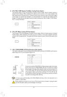
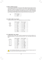
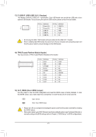
12 1 23 S3 S3 B SS S S U B SS S U 1 23 __ 3 __ 3 8) SATA EXPRESS (SATA Express Connectors) Each SATSA Ex_press connector supports a single SATA Express device. SF S_ SF _ _ DEBUG PORT S3 B SS S U DEBUG PORT B_ S _S _ B_ S _S _ 9) SATA3 0/1/2/3/4/5 (SATAS 6G_b/s Connectors) The SATA connectors conform to SATA 6Gb/s standard and are compatible wSithF SATA 3Gb/s and SATA_ 1.5Gb/s standard. Each SATA connector supports a single SATA device. The Intel® Chipset supports RAID 0, RAID 1, RSAID _5, and RAID 10. Refer to Chapter 3, "Configuring a RAID Set," for instructions on configuring a RSAID_ array. _ _B _ _B Pin No. Definition SATA3 2 3 SATA3 5 4 10 1 GND B_ 2 TXP S _S _ 1 7 7 1 3 TXN _ 7 1 7 1 4 G_ ND 5 RXN S_ 6 RXP 7 GND S_ To enable hot-plugging for the SATA ports, refer to Chapter 2, "BIOS Setup," "Peripherals\SATA S _And RST Configuration," for more information. _ 10) U2_32G (U.2 Connector) The U.2 connector supports a single U.2 device. Please note that a U.2 SSD cannot be used to create a RAID set either with an M.2 SATA SSD or a SATA hard drive. To create a RAID array with a U.2 SSD, you must set up the configuration in UEFI instructions on configuring aSRAI_D array. BIOS mode. Refer to Chapter 3, "Configuring a RB_AID Set," for U B_ USB 0_ B B_ U B_ USB 0_ B F_USB3 F_USB3 U B_ - 17 - B_ USB 0_ B
-
 1
1 -
2
-
3
-
4
-
5
-
6
-
7
-
8
-
9
-
10
-
11
-
 12
12 -
 13
13 -
 14
14 -
 15
15 -
 16
16 -
 17
17 -
 18
18 -
 19
19 -
 20
20 -
 21
21 -
 22
22 -
23
-
24
-
25
-
26
-
27
-
28
-
29
-
30
-
31
-
32
-
33
-
34
-
35
-
36
-
37
-
38
-
39
-
40
-
41
-
42
-
43
-
44
-
45
-
46
-
47
-
48
 |
 |