Gigabyte J4005N D2P User Manual - Page 11
ATX_12V/ATX 2x2 12V Power Connector and 2x12 Main Power Connector, 4 SOC_FAN/SYS_FAN1 Fan Headers
 |
View all Gigabyte J4005N D2P manuals
Add to My Manuals
Save this manual to your list of manuals |
Page 11 highlights
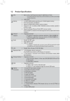
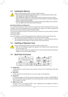
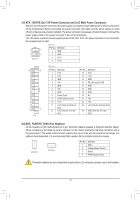
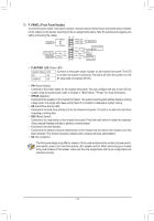
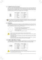
1/2) ATX_12V/ATX (2x2 12V Power Connector and 2x12 Main Power Connector) With the use of the power connector, the power supply can supply enough stable power to all the components on the motherboard. Before connecting the power connector, first make sure the power supply is turned off and all devices are properly installed. The power connector possesses a foolproof design. Connect the power supply cable to the power connector in the correct orientation. The 12V power connector mainly supplies power to the CPU. If the 12V power connector is not connected, the computer will not start. ATX_12V: Pin No. Definition 3 4 1 GND 1 2 2 GND ATX_12V 3 +12V 4 +12V 12 24 1 13 ATX ATX_12V: Pin No. 1 2 3 4 5 6 7 8 9 10 11 12 Definition 3.3V 3.3V GND +5V GND +5V GND Power Good 5VSB (stand by +5V) +12V +12V (Only for 2x12-pin ATX) 3.3V (Only for 2x12-pin ATX) Pin No. 13 14 15 16 17 18 19 20 21 22 23 Definition 3.3V -12V GND PS_ON (soft On/Off) GND GND GND NC +5V +5V +5V (Only for 2x12-pin ATX) 24 GND (Only for 2x12-pin ATX) 3/4) SOC_FAN/SYS_FAN1 (Fan Headers) All fan headers on this motherboard are 4-pin. Most fan headers possess a foolproof insertion design. When connecting a fan cable, be sure to connect it in the correct orientation (the black connector wire is the ground wire). The speed control function requires the use of a fan with fan speed control design. For optimum heat dissipation, it is recommended that a system fan be installed inside the chassis. 1 SOC_FAN 1 SYS_FAN1 Pin No. 1 2 3 4 Definition GND Voltage Speed Control Sense PWM Speed Control These fan headers are not configuration jumper blocks. Do not place a jumper cap on the headers. - 11 -
-
 1
1 -
2
-
3
-
4
-
5
-
 6
6 -
 7
7 -
 8
8 -
 9
9 -
 10
10 -
 11
11 -
 12
12 -
 13
13 -
 14
14 -
 15
15 -
 16
16 -
17
-
18
-
19
-
20
-
21
-
22
-
23
-
24
-
25
-
26
-
27
-
28
-
29
-
30
 |
 |
