Gigabyte J4005N D2P User Manual - Page 12
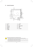
SATA3 0/1 SATA 6Gb/s Connectors, M2I_10G M.2 Socket 3 Connector
 |
View all Gigabyte J4005N D2P manuals
Add to My Manuals
Save this manual to your list of manuals |
Page 12 highlights
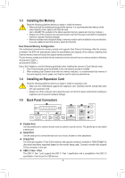
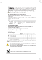
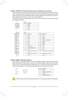
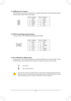
DEBUGDEBUG PORT PORT 123 SS U F_ 5) SATA3 0/1 (SATA 6Gb/s Connectors) The SATA connectors conform to SATA 6Gb/s standard and are compatible with SATA 3Gb/s and SATA 1.5Gb/s standard. Each SATA connector supports a single SATA device. SATA3 01 11 Pin No. 1 2 3 Definition GND TXP TXN 4 GND 77 5 RXN _ B S_ 6 RXP B B 7 GND S B_ B 6) M2I_10G (M.2 Socket 3 Connector) The M.2 connector supports M.2 SATA SSDs and M.2 PCIe SSDs. S S _S S_ _ B _U _ B F_USB3 F _ S_ 80 60 42 Follow the steps below to correctly install an M.2 SSD in the M.2 connector. Step 1: Use a screw driver to unfasten the screw and nut from the motherboard. Locate the proper mounting hole for the M.2 SSD to be installed and then screw the nut first. Step 2: F Slide the M.2 SSD into the connector at an angle. Step 3: Press the M.2 SSD down and then secure it with the screw. Select the proper hole for the M.2 SSD to be installed and refasten the screw and nut. _0 Installation Notices for the M.2 and SATA Connectors: Due to the limited number of lanes provided by the Chipset, the availability of the SATA connectors may be affected by the type of device installed in the M.2 connector. The M2I_10G connector shares bandwidth with the SATA3 1 connector. Refer to the following table for details. Type of M.2 SSD Connector SATA3 0 _ F SATA3 1 M.2 SATA SSD a r M.2 PCIe SSD a a No M.2 SSD Installed a a: Available, r: Not available _0 F a - 12 -
-
 1
1 -
2
-
3
-
4
-
5
-
6
-
 7
7 -
 8
8 -
 9
9 -
 10
10 -
 11
11 -
 12
12 -
 13
13 -
 14
14 -
 15
15 -
 16
16 -
 17
17 -
18
-
19
-
20
-
21
-
22
-
23
-
24
-
25
-
26
-
27
-
28
-
29
-
30
 |
 |
