Gigabyte M10RDI Manual
Gigabyte M10RDI Manual
 |
View all Gigabyte M10RDI manuals
Add to My Manuals
Save this manual to your list of manuals |
Gigabyte M10RDI manual content summary:
- Gigabyte M10RDI | Manual - Page 1
M10RDI Intel Atom Mini ITX Motherboard with Intel ICH10R Chipset User's Manual 1st Ed - 11 January 2013 - Gigabyte M10RDI | Manual - Page 2
IN ACCORDANCE WITH THE INSTRUCTION MANUAL, MAY CAUSE HARMFUL guide is designed for experienced users to setup the system within the shortest time. For detailed information, please always refer to the electronic user's manual. Copyright Notice Copyright 2013 Gigabyte Technology M10RDI User's Manual - Gigabyte M10RDI | Manual - Page 3
that are described in this manual are for illustration purposes only. Gigabyte Technology Inc. makes no representation or warranty that such application will be suitable for the specified use without further testing or modification. Life Support Policy Gigabyte Technology's PRODUCTS ARE NOT FOR USE - Gigabyte M10RDI | Manual - Page 4
M10RDI Your satisfaction is our primary concern. Here is a guide to Gigabyte's customer services. To ensure you get the full benefit of our services, please follow the instructions below carefully. Technical Support We want you to get the maximum performance from your products. So if you run into - Gigabyte M10RDI | Manual - Page 5
repair service. If any of Gigabyte's Gigabyte's products model name, hardware & BIOS revision number, other hardware and software used, etc.) Note anything abnormal and list any on-screen messages you get when the problem occurs. 2. Call your dealer and describe the problem. Please have your manual - Gigabyte M10RDI | Manual - Page 6
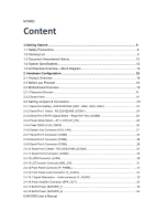
M10RDI Content 1.Getting Started ...9 1.1 Safety Precautions 9 1.2 Packing List ...9 1.3 Document Amendment History 10 1.4 System Specifications 12 1.5 Architecture Overview - Block Diagram 14 2. Hardware Configuration 15 2.1 Product Overview ...16 2.2 Before you Proceed 18 2.3 Motherboard - Gigabyte M10RDI | Manual - Page 7
's Manual 2.4.19 USB Connector (F_USB1) ...34 2.4.20 USB Connector (F_USB2) ...35 2.4.21 GPIO Connector (GPIO_CNT 35 2.4.22 Low Pin Count Connector (LPC) ...36 3. BIOS Setup ...37 3.1 Introduction ...38 3.2 Starting Setup ...38 3.3 Using Setup ...39 3.4 Getting Help ...40 3.5 In Case of Problems - Gigabyte M10RDI | Manual - Page 8
M10RDI 3.6.5.2 User Password ...55 3.6.6 Save & Exit ...56 3.6.6.1 Save Changes and Exit ...56 3.6.6.2 Discard Changes and Exit ...57 Defaults ...57 3.6.6.8 Save as user defaults ...57 3.6.6.9 Restore user defaults ...57 3.6.6.10 Boot override ...57 4. Mechanical Drawing ...58 8 M10RDI User's Manual - Gigabyte M10RDI | Manual - Page 9
instructions in any circumstance. If you really have to do this, please contact us for further support. 1.2 Packing List Before you begin installing your single board, please make sure that the following materials have been shipped: 1 x M10RDI Mini-ITX Motherboard 1 x CD-ROM contains OS drivers - Gigabyte M10RDI | Manual - Page 10
M10RDI 1.3 Document Amendment Histoy Revision 1st Date January 2013 Comment Initial Release 10 M10RDI User's Manual - Gigabyte M10RDI | Manual - Page 11
User's Manual This manual describes in detail the Gigabyte Technology M10RDI Single Board. We have tried to any suggestions or find any errors concerning this manual and want to inform us of these, please contact our Customer Service department with the relevant details. M10RDI User's Manual 11 - Gigabyte M10RDI | Manual - Page 12
Option) AMI 16Mb SPI BIOS Intel® ICH10R ITE8783+ FINTEK F81214 2x 204-pin DDR3 SODIMM, up to 4GB (N2600 support 1 x DDR3 SODIMM only) H/W Reset : 1 to 255 sec/min per step (Option) Monitoring temperature, voltage chip 2 x Realtek 8111E 10/100/1000 Gigabit Ethernet Compatible 12 M10RDI User's Manual - Gigabyte M10RDI | Manual - Page 13
1 PS/2 Mini-Din (KB/MS support by external Y-cable) 2 USB Connectors each supports 2 USB Ports 4 COM RS-232 Connectors 4 SATA II Connectors, RAID 0,1,5,10 supported 2 SATA Power Connectors 1 Front Panel , non-condensing 6.69" x 6.69" (170 x 170 mm) 0.77 Ibs (0.35 Kg) M10RDI User's Manual 13 - Gigabyte M10RDI | Manual - Page 14
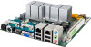
M10RDI 1.5 Architecture Overview - Block Diagram The following block diagram shows the architecture and main components of M10RDI 14 M10RDI User's Manual - Gigabyte M10RDI | Manual - Page 15
2. Hardware Configuration User's Manual M10RDI User's Manual 15 - Gigabyte M10RDI | Manual - Page 16
/s • Provides 10/100/1000 Mbps solution to your network or broadband connection without having to buy an • Onboard audio CODEC supports uncompromising DVD audio quality, bringing a move vivid sound experience and high‐quality audio without having to buy advanced sound cards. 16 M10RDI User's Manual - Gigabyte M10RDI | Manual - Page 17
User's Manual • Main Memory M10RDI provides 2x 204-pin DDR3 SODIMM, up to 4GB (N2600 support 1 x DDR3 SODIMM only). *SODIMM module. Note: (1) Please do not change any DDR SDRAM parameter in end from the processor. Here, SODIMM2 is situated at the far end from the processor. M10RDI User's Manual 17 - Gigabyte M10RDI | Manual - Page 18
Before you Proceed Take note of the following precautions before you install motherboard components or change any motherboard settings. Unplug the power cord from the wall socket before touching so may cause severe damage to the motherboard, peripherals, and/or components. 18 M10RDI User's Manual - Gigabyte M10RDI | Manual - Page 19
Manual Before you install the motherboard, study the configuration of your chassis to ensure that the motherboard fits into it. Refer to the chassis documentation before installing the motherboard. Make sure to unplug the power cord before installing or removing the motherboard the motherboard to - Gigabyte M10RDI | Manual - Page 20
M10RDI 20 M10RDI User's Manual - Gigabyte M10RDI | Manual - Page 21
you would connect either two pins. The jumper settings are schematically depicted in this manual as follows: A pair of needle-nose pliers may be helpful when working with 54 mm 3 x 1 header, pitch 2.00 mm 2 x 1 header, pitch 2.54 mm Connectors Labe l Function Note M10RDI User's Manual 21 - Gigabyte M10RDI | Manual - Page 22
M10RDI ATX_12V SODIMM1 SODIMM2 SYS_FAN COM1 COM2 COM3 COM4 COM5 COM6 LVDS BKL_CN USB_LAN1 USB_LAN2 KB_MS HDMI VGA Min_PCIE1 Min_PCIE2 2.54mm 5 x 2 wafer, pitch 2.54 mm 5 x 2 wafer, pitch 2.54 mm 6 x 2 wafer, pitch 2.00 mm 7 x 2 wafer, pitch 2.00 mm 5 x 2 wafer, pitch 2.54 mm 22 M10RDI User's Manual - Gigabyte M10RDI | Manual - Page 23
& Connectors 2.4.1 Serial Port 1 Setting ‐ RS232/422/485 (JRS1, JRS2, JRS3, JRS4) User's Manual RS23 2* RS422/ RS485 *De fault RS422/485 Pin Mapping Pin RS-232 RS-485 RS-422 1 DCD TXD - TXD- 2 RXD TXD + TXD+ 3 TXD RXD+ 4 DTR RXD- 5 GND GND GND M10RDI User's Manual 23 - Gigabyte M10RDI | Manual - Page 24
M10RDI 2.4.2 Serial Port 1 Select - RS232/422/485(JCOM1) RS232* RS422 RS485 *De fault Signal RXD232 RXD422 RXD485 PIN PIN 12 34 56 Signal RXD1 RXD1 RXD1 24 M10RDI User's Manual - Gigabyte M10RDI | Manual - Page 25
2.4.3 Serial Port 3 RI Pin Signal Select - Ring/+5V/+12V (JCOM3) User's Manual +5V Ring* +12V *De fault Signal VCC NRI3+12V PIN PIN Signal 1 2 RI3-/5V/12 3 4 RI3-/5V/12 5 6 RI3-/5V/12 M10RDI User's Manual 25 - Gigabyte M10RDI | Manual - Page 26
M10RDI 2.4.4 Power Mode Select - AT or ATX(AT_CN) ATX* AT *De fault 2.4.5 Clear CMOS(CLR_CMOS) Signal PIN NC 3 PWR_F_BTN# 2 AT_PWR_F_BT 1 Normal* Clear *Default 26 M10RDI User's Manual Signal PIN -RTCRST 1 GND 2 - Gigabyte M10RDI | Manual - Page 27
2.4.6 System Fan Connector (SYS _FAN) User's Manual Signal PIN GND 1 +12V 2 FANIO2 3 PWM Input 4 2.4.7 Serial Port 3 Connector (COM3) Signal PIN PIN NC 9 10 NCTS3- 7 8 NDSR3- 5 6 NDTR3- 3 4 NRXD3- 1 2 Signal NRI3NRTS3GND NTXD3NDCD3- M10RDI User's Manual 27 - Gigabyte M10RDI | Manual - Page 28
(COM4) Signal PIN PIN NC 9 10 NCTS4- 7 8 NDSR4- 5 6 NDTR4- 3 4 NRXD4- 1 2 Signal NRI4NRTS4GND NTXD4NDCD4- 2.4.9 Serial Port 5 Connector (COM5) 28 M10RDI User's Manual Signal PIN PIN NC 9 10 NCTS5- 7 8 NDSR5- 5 6 NDTR5- 3 4 NRXD5- 1 2 Signal NRI5NRTS5GND NTXD5NDCD5- - Gigabyte M10RDI | Manual - Page 29
2.4.10 Serial Port 5 RI Pin Signal Select - Ring/+5V/+12V (JCOM5) User's Manual +5V Ring* +12V *De fault 2.46.11 Serial Port 6 Connector (COM6) Signal 12 Signal NC NCTS5NDSR5NDTR5NRXD5- PIN PIN 9 10 Signal NRI5- 7 8 NRTS5- 5 6 GND 3 4 NTXD5- 1 2 NDCD5- M10RDI User's Manual 29 - Gigabyte M10RDI | Manual - Page 30
M10RDI 2.4.12 LVDS Connector (LVDS) Signal VCC3 PIN PIN 1 2 Signal VCC VCC3 3 4 VCC SCL1 5 6 SDA1 GND 7 8 GND +RXO1_C 9 10 +RXO0_C -RXO1_C GND 31 32 GND +RXECLKE_C 33 34 +RXECLKO_C -RXECLKE_C 35 GND 37 36 -RXECLKO_C 38 GND +12V 39 40 +12V 30 M10RDI User's Manual - Gigabyte M10RDI | Manual - Page 31
13 LCD Inverter Connector (BKL_CN) User's Manual 2.4.14 Front Panel Connector (F_PANEL) Signal PIN +12V 5 GND 4 BKLTEN 3 BKLTCTL 2 VCC 1 Signal PIN PIN Signal -INTRUDER 9 10 NC -SYS_RST 7 8 GND GND 5 6 PWR BTN# SATALED- 3 4 GND HD+ 1 2 MPD+ M10RDI User's Manual 31 - Gigabyte M10RDI | Manual - Page 32
M10RDI 2.3.15 Front Panel Audio Connector (F_AUDIO) Signal PIN PIN Signal GND 2 1 MIC_L -ACZ_DET 4 3 MIC_R SRTN1 6 5 HPOUT_R_H NC 8 7 FAUDIO_JD SRTN2 Jack detection for front panel microphone Jack detection for front panel headphone Front panel jack detect 32 M10RDI User's Manual - Gigabyte M10RDI | Manual - Page 33
2.4.16 Audio Amplifier Connector (SPK_OUT) User's Manual 2.4.17 SATA Power (SATAPW_1) Signal PIN OUT_L+ 4 OUT_L- 3 OUT_R - 2 OUT_R+ 1 Signal PIN +12V 1 GND 2 GND 3 VCC 4 M10RDI User's Manual 33 - Gigabyte M10RDI | Manual - Page 34
M10RDI 2.4.18 SATA Power (SATAPW_2) 2.4.19 USB Connector (F_USB1) Signal PIN +12V 1 GND 2 GND 3 VCC 4 34 M10RDI User's Manual Signal PIN USB Power 2 USBP0- 4 USBP0+ 6 GND 8 GND 10 PIN Signal 1 USB Power 3 USBP1- 5 USBP1+ 7 GND 9 NC - Gigabyte M10RDI | Manual - Page 35
2.4.20 USB Connector (F_USB2) User's Manual Signal PIN USB Power 2 USBP0- 4 USBP0+ 6 GND 8 GND 10 PIN Signal 1 USB Power 3 USBP1- 5 11 12 GND SMBCLK 9 10 SMBDATA SOGP0_ 7 8 SOGPI_4 SOGP0_ 5 6 SOGPI_3 SOGP0_ 3 4 SOGPI_2 SOGP0_ 1 2 SOGPI_1 M10RDI User's Manual 35 - Gigabyte M10RDI | Manual - Page 36
M10RDI 2.4.22 Low Pin Connector (LPC) Signal -LDRQ1 PIN PIN Signal 13 14 5VDUAL GND 11 12 VCC GND 9 LPC_CLK 7 10 SERIRQ 8 LAD3 -LFRAME 5 6 LAD2 -PFMRST 3 4 LAD1 VCC3 1 2 LAD0 36 M10RDI User's Manual - Gigabyte M10RDI | Manual - Page 37
3.BIOS Setup User's Manual M10RDI User's Manual 37 - Gigabyte M10RDI | Manual - Page 38
M10RDI 3.1 Introduction The BIOS setup program allows users to modify the basic system configuration. In this following chapter will describe how to access the boot, an error message will be displayed and you will again be asked to. Press F1 to Continue, DEL to enter SETUP 38 M10RDI User's Manual - Gigabyte M10RDI | Manual - Page 39
User's Manual 3.3 Using Setup In general, you use the arrow keys to highlight items, press to select, use the PageUp and PageDown keys to Sub Menu Use the arrow keys to move the cursor to the sub menu you want. Then press . A "" pointer marks all sub menus. M10RDI User's Manual 39 - Gigabyte M10RDI | Manual - Page 40
F1 key again. 3.5 In Case of Problems If, after making and saving system changes with Setup, you discover that your computer no longer is able to boot, the AMI BIOS supports an override to the CMOS settings which resets has the potential for causing you to use the override. 40 M10RDI User's Manual - Gigabyte M10RDI | Manual - Page 41
time. Manually enter the hours, minutes and seconds. Note: BIOS setup screens shown in this chapter are for reference only, and may not exactly match what you see on your screen. Visit the Gigabyte website (www.gigabyte.tw) to download the latest product and BIOS information. M10RDI User's Manual 41 - Gigabyte M10RDI | Manual - Page 42
M10RDI 3.6.2 Advanced BIOS settings This section allows you to configure your CPU and other system devices for basic operation through the following to RAM) [Default] D escription Select the highest ACPI sleep state the system will enter when the SUSPEND button is pressed 42 M10RDI User's Manual - Gigabyte M10RDI | Manual - Page 43
3.6.2.2 S5 RTC Wake settings User's Manual Item Wake system with Fixed Time Wake system with Dynamic Time Options Enabled Disabled[Default] Enabled wake on alarm event. When enabled, System will wake on the current time + Increase minutes (s) 3.6.2.3 SATA Configuration M10RDI User's Manual 43 - Gigabyte M10RDI | Manual - Page 44
Item SATA Mode Serial-ATA Controller 0 Serial-ATA Controller 1 eSATA Port Support Options Disabled IDE Mode[Default] ACHI Mode RAID Mode Enabled Disabled Compatible[Default Enable/ Disable Serial ATA Controller 0. Enable/ Disable Serial ATA Controller 1. eSATA Port Support. 44 M10RDI User's Manual - Gigabyte M10RDI | Manual - Page 45
's Manual 3.6.2.4 USB Configuration The USB configuration menu is used to read USB configuration information and configure USB. Item Legacy USB support USB_DRIVE 1.00 Options Enabled[Default] Disabled Auto Auto[Default] Floppy Forced FDD Hard Disk CD‐ROM Descr iption Enables Legacy USB support - Gigabyte M10RDI | Manual - Page 46
Configuration Serial Port 2 Configuration 3.6.2.5.1 Serial Port 1 Configuration Description Set Parameters of Serial Port 1 (COM1). Set Parameters of Serial Port 2 (COM2). Item Serial Port 46 M10RDI User's Manual Options Enabled Disabled[Default] De scription Enable or Disable Serial Port (COM). - Gigabyte M10RDI | Manual - Page 47
3.6.2.5.2 Serial Port 2 Configuration User's Manual Item Serial Port Options Enabled Disabled[Default] De scription Enable or Disable Serial Port (COM). M10RDI User's Manual 47 - Gigabyte M10RDI | Manual - Page 48
M10RDI 3.6.2.6 IT8783F Super IO Configuration You can use this item to set up or change the IT8783F Super IO configuration for serial ports. Please 3 (COM3) Set Parameters of Serial Port 4 (COM4) Set Parameters of Serial Port 5 (COM5) Set Parameters of Serial Port 6 (COM6) 48 M10RDI User's Manual - Gigabyte M10RDI | Manual - Page 49
Configuration User's Manual Item Serial Port Options Enabled Disabled[Default] 3.6.2.6.2 Serial Port 4 Configuration De scription Enable or Disable Serial Port (COM). Item Serial Port Options Enabled Disabled[Default] De scription Enable or Disable Serial Port (COM). M10RDI User's Manual 49 - Gigabyte M10RDI | Manual - Page 50
Serial Port 5 Configuration Item Serial Port Options Enabled Disabled[Default] 3.6.2.6.4 Serial Port 6 Configuration De scription Enable or Disable Serial Port (COM). Item Serial Port 50 M10RDI User's Manual Options Enabled Disabled[Default] De scription Enable or Disable Serial Port (COM). - Gigabyte M10RDI | Manual - Page 51
User's Manual 3.6.2.7 IT8783F H/W Monitor The H/W Monitor shows the operating temperature, fan speeds and system voltages. M10RDI User's Manual 51 - Gigabyte M10RDI | Manual - Page 52
M10RDI 3.6.3 Advanced Chipset Features Item Restore AC Power Loss Azalia HD Audio Onboard LAN1 LAN PXE ROM Onboard LAN2 LAN PXE ROM Mini PCIE1 or Disable the PCI Express Ports in the Chipset. Enable or Disable the PCI Express Ports in the Chipset. Config Intel IGD Settings. 52 M10RDI User's Manual - Gigabyte M10RDI | Manual - Page 53
3.6.3.1 Intel IGD Configuration User's Manual Item IGFX - Boot Type Fixed Graphics Memory Size LVDS Backlight PWM Panel ID Options VBIOS Default[Default] CRT if external graphics present. Configure Fixed Graphics Memory Size. LVDS Backlight PWM Configuration. Panel ID. M10RDI User's Manual 53 - Gigabyte M10RDI | Manual - Page 54
M10RDI 3.6.4 Boot settings Item Setup Prompt Timeout Bootup NumLock State Options 1~65535 On [Default] Off De scription Number of seconds to wait for of multiple Option ROMs(Legacy and EFI Compatible),specifies what PCI Option ROM to launch. Sets the system boot order 54 M10RDI User's Manual - Gigabyte M10RDI | Manual - Page 55
3.6.5 Security Use the Security menu to set system and user password. User's Manual 3.6.5.1 Administrator Password This setting specifies a password that must be entered to access the program, the User will have Administrator rights. By default, no password is specified. M10RDI User's Manual 55 - Gigabyte M10RDI | Manual - Page 56
M10RDI 3.6.6 Save & Exit 3.6.6.1 Save Changes and Exit Use the save changes and reset option to save the changes made to the BIOS options and to exit the BIOS configuration setup program. 56 M10RDI User's Manual - Gigabyte M10RDI | Manual - Page 57
User's Manual 3.6.6.2 Discard Changes and Exit Use the Discard changes and Exit option to exit the system without saving the changes made to the . If BIOS setup options have been changed and saved, a reboot will be required and the boot override selection will not be valid. M10RDI User's Manual 57 - Gigabyte M10RDI | Manual - Page 58
M10RDI 4.Mechanical Drawing 58 M10RDI User's Manua - Gigabyte M10RDI | Manual - Page 59
User's Manual M10RDI User's Manual 59
-
 1
1 -
 2
2 -
 3
3 -
 4
4 -
 5
5 -
 6
6 -
 7
7 -
8
-
9
-
10
-
11
-
12
-
13
-
14
-
15
-
16
-
17
-
18
-
19
-
20
-
21
-
22
-
23
-
24
-
25
-
26
-
27
-
28
-
29
-
30
-
31
-
32
-
33
-
34
-
35
-
36
-
37
-
38
-
39
-
40
-
41
-
42
-
43
-
44
-
45
-
46
-
47
-
48
-
49
-
50
-
51
-
52
-
53
-
54
-
55
-
56
-
57
-
58
-
59
 |
 |

M10RDI
Intel Atom Mini ITX Motherboard
with Intel ICH10R Chipset
User’s Manual
1
st
Ed – 11 January 2013