Gigabyte M10RDI Manual - Page 21
umpers, onnector
 |
View all Gigabyte M10RDI manuals
Add to My Manuals
Save this manual to your list of manuals |
Page 21 highlights
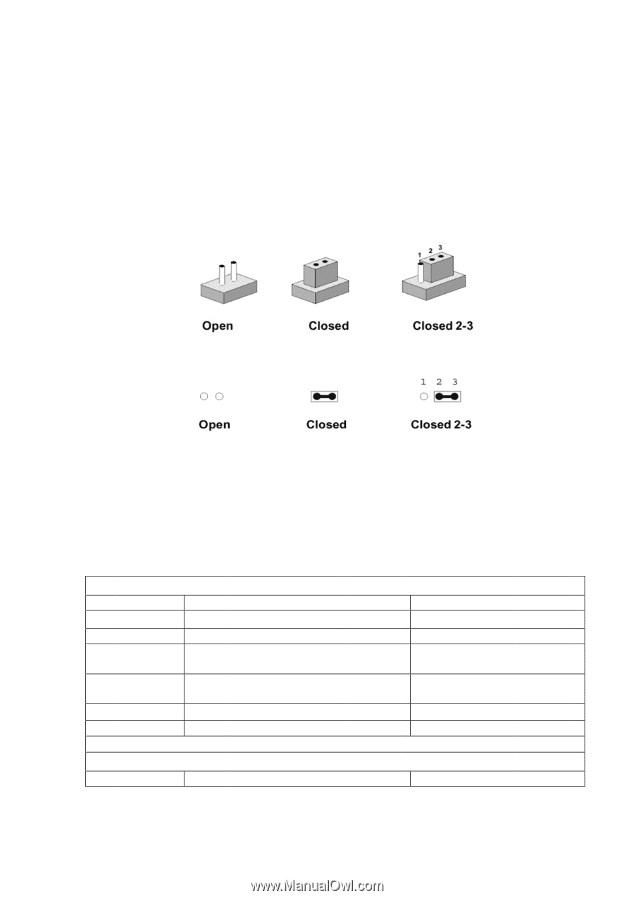
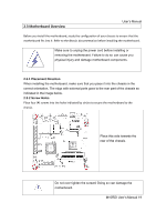
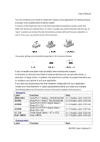
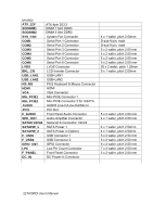
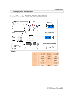
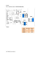
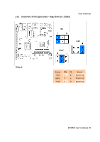
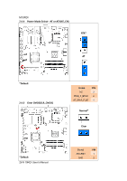
User's Manual You can configure your board to match the needs of your application by setting jumpers. A jumper is the simplest kind of electric switch. It consists of two metal pins and a small metal clip (often protected by a plastic cover) that slides over the pins to connect them. To "close" a jumper you connect the pins with the clip. To "open" a jumper you remove the clip. Sometimes a jumper will have three pins, labeled 1, 2, and 3. In this case, you would connect either two pins. The jumper settings are schematically depicted in this manual as follows: A pair of needle-nose pliers may be helpful when working with jumpers. Connectors on the board are linked to external devices such as hard disk drives, a keyboard, or floppy drives. In addition, the board has a number of jumpers that allow you to configure your system to suit your application. If you have any doubts about the best hardware configuration for your application, contact your local distributor or sales representative before you make any changes. The following tables list the function of each of the board's jumpers and connectors. Jumpers Label JRS1/2/3/4 JCOM1 JCOM3 JCOM5 AT_CN CLR_CMOS Function Serial Port 1 Setting - RS232/422/485 Serial Port 1 Select - RS-232/422/485 Serial Port 3 RI Pin Signal Select - Ring/+5V/+12V Serial Port 5 RI Pin Signal Select - Ring/+5V/+12V Power Mode Select - AT or ATX Clear CMOS Note 3 x 1 header, pitch 2.00 mm 3 x 2 header, pitch 2.00 mm 3 x 2 header, pitch 2.54 mm 3 x 2 header, pitch 2.54 mm 3 x 1 header, pitch 2.00 mm 2 x 1 header, pitch 2.54 mm Connectors Labe l Function Note M10RDI User's Manual 21
-
 1
1 -
2
-
3
-
4
-
5
-
6
-
7
-
8
-
9
-
10
-
11
-
12
-
13
-
14
-
15
-
 16
16 -
 17
17 -
 18
18 -
 19
19 -
 20
20 -
 21
21 -
 22
22 -
 23
23 -
 24
24 -
 25
25 -
 26
26 -
27
-
28
-
29
-
30
-
31
-
32
-
33
-
34
-
35
-
36
-
37
-
38
-
39
-
40
-
41
-
42
-
43
-
44
-
45
-
46
-
47
-
48
-
49
-
50
-
51
-
52
-
53
-
54
-
55
-
56
-
57
-
58
-
59
 |
 |