Gigabyte Z490M GAMING X User Manual - Page 19
F_U32 USB 3.2 Gen 1 Header, F_USB1/F_USB2 USB 2.0/1.1 Headers, SPI_TPM Trusted Platform Module Header
 |
View all Gigabyte Z490M GAMING X manuals
Add to My Manuals
Save this manual to your list of manuals |
Page 19 highlights
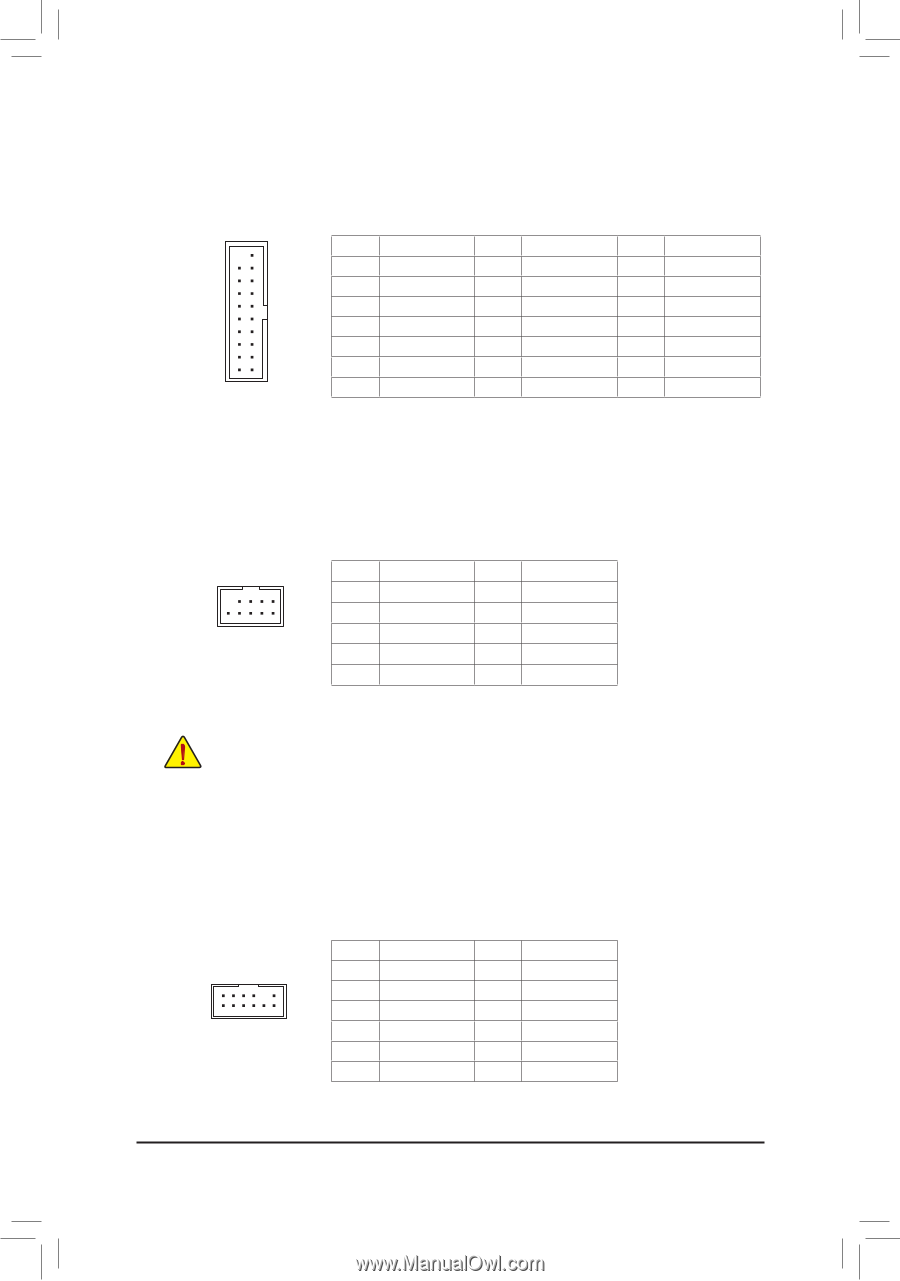
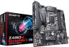
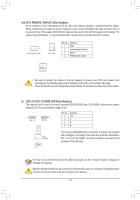
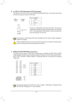
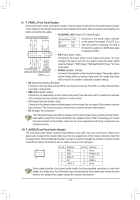
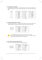
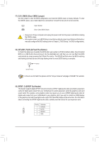
1 23 1 123 F_USB30 F_ U SS U F_ 11)F_F_U32 (USB 3.2 Gen 1 HeG.aQdBeOrF)M The header conforms to USB 3.2 Gen 1 and USB 2.0 specification and can provide two USB ports. For purchasing the optional 3.5" front panel that provides two USB 3.2 Gen 1 ports, please contact the local dealer. 20 1 Pin No. Definition 1 VBUS Pin No. Definition 8 D1- Pin No. Definition 15 SSTX2- 2 SSRX1- 9 D1+ 16 GND 3 B_ 4 SSRX1+ GND 10 NC B SS 11 D2+ 17 SSRX2+ 18 SSRX2- 5 SSTX1- 12 D2-1 19 VBUS 11 10 6 SSTX1+ 7 GND 13 GND 14 SSTX2+ 20 _S No Pin 1 23 1 1 23 1 _ B S_ B B S 12) F_USB1/F_USB2 (USB 2.0/1.1 Headers) The headers conform to USB 2.0/1.1 specification. Each USB header can provide two USB ports via an optional USB bracket. For purchasing the optional USB bracket, please contact the local dealer. 1 23 S B_ B S 9 1 Pin No. Definition Pin No. Definition S S 1 Power (5V) 6 USB DY+ 2 Power (5V) 7 GND 10 2 _S 3 USB DX4 USB DY- 8 GND 9 No Pin S_ 5 USB DX+ 10 NC _ B •• Do not plug the IEEE 1394 bracket (2x5-pin) cable into the USB 2.0/1.1 header. _U _ B •• SPrio3r from to installing the USB brBacSkSet, beSsure to turn off your compuUter the power outlet to prevent damage to the USFB bracket. and unplug the po_w_er cor3d _ _B F_USB3 F S_ SF 13) SPI_TPM (Trusted Platform Module Header) _ 0 _ You may connect an SPI TPM (Trusted Platform Module) to this header. _ 1S1 _ 1 12 2 S_ Pin No. Definition 1 Data Output 2 3 B_ Power No Pin (3.3V) S 4 NC 5 Data Input 6 CLK Pin No. Definition 7 Chip Select 8 _S 9 _ F GND_ IRQ 10 NC 11 NC 12 RST - 19 - _0 F _ _B _ S F_ _ S F_
-
 1
1 -
2
-
3
-
4
-
5
-
6
-
7
-
8
-
9
-
10
-
11
-
12
-
13
-
 14
14 -
 15
15 -
 16
16 -
 17
17 -
 18
18 -
 19
19 -
 20
20 -
 21
21 -
 22
22 -
 23
23 -
 24
24 -
25
-
26
-
27
-
28
-
29
-
30
-
31
-
32
-
33
-
34
-
35
-
36
-
37
-
38
-
39
-
40
-
41
-
42
-
43
-
44
-
45
-
46
-
47
-
48
 |
 |