Hamilton Beach 990 Operation Manual - Page 9
Cleaning, Instructions continued
 |
UPC - 040094019908
View all Hamilton Beach 990 manuals
Add to My Manuals
Save this manual to your list of manuals |
Page 9 highlights
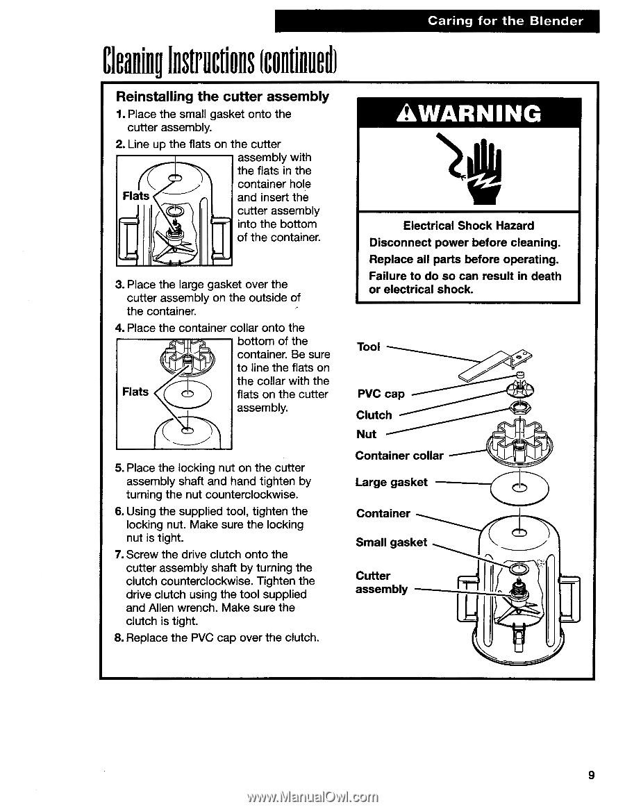
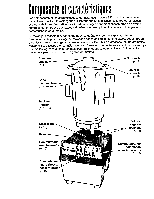
Caring for the Blender CleaningInstructions(continued) Reinstalling the cutter assembly 1. Place the small gasket onto the cutter assembly. 2. Line up the flats on the cutter assembly with the flats in the container hole Flats 0 and insert the t- - cutter assembly into the bottom of the container. 3.Place the large gasket over the cutter assembly on the outside of the container. 4. Place the container collar onto the bottom of the container. Be sure to line the flats on Flats the collar with the flats on the cutter assembly. 5. Place the locking nut on the cutter assembly shaft and hand tighten by turning the nut counterclockwise. 6. Using the supplied tool, tighten the locking nut. Make sure the locking nut is tight. 7. Screw the drive clutch onto the cutter assembly shaft by turning the clutch counterclockwise. Tighten the drive clutch using the tool supplied and Allen wrench. Make sure the clutch is tight. 8. Replace the PVC cap over the clutch. AWARNING Electrical Shock Hazard Disconnect power before cleaning. Replace all parts before operating. Failure to do so can result in death or electrical shock. Tool PVC cap Clutch Nut Container collar Large gasket Container Small gasket Cutter assembly 9
-
 1
1 -
2
-
3
-
 4
4 -
 5
5 -
 6
6 -
 7
7 -
 8
8 -
 9
9 -
 10
10 -
 11
11 -
 12
12 -
 13
13 -
 14
14 -
15
-
16
-
17
-
18
-
19
-
20
-
21
-
22
-
23
-
24
-
25
-
26
-
27
-
28
-
29
-
30
-
31
-
32
-
33
-
34
 |
 |