Harman Kardon AVR 140 Owners Manual - Page 17
Input Setup, Audio Setup - manual
 |
View all Harman Kardon AVR 140 manuals
Add to My Manuals
Save this manual to your list of manuals |
Page 17 highlights
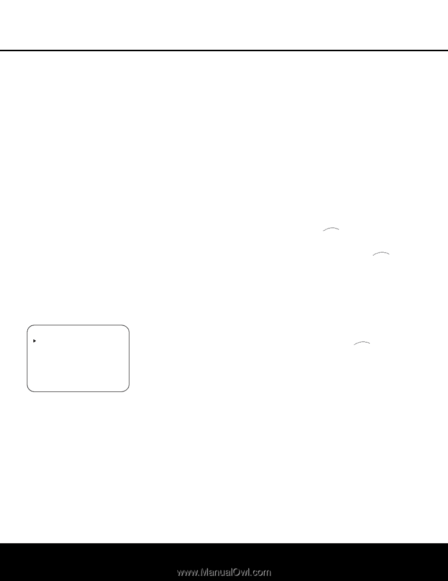
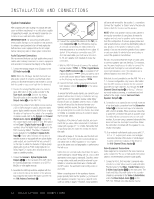
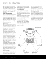
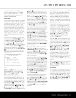
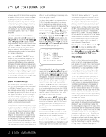
SYSTEM CONFIGURATION in a prior menu item. It is recommended that you record your settings for each input using the worksheets in the appendix to this manual, in the event there is a power loss or if you need to reenter the settings for some other reason. Input Setup The first step in configuring the AVR 140 is to configure each input. Once an input is configured, all settings for the Digital Input, Component Video Input and Surround Mode will "attach" themselves to that input and be stored in a nonvolatile memory. The later selection of that input will automatically recall those settings. For that reason, the procedures described below must be repeated for each input source so that you have the opportunity to customize each source to your specific listening requirements. However, once made, they need not be changed again unless you need to alter a setting. When using the full-OSD system to make the setup adjustments, press the OSD Button v once so that the MASTER MENU (Figure 1) appears. The › cursor will be next to the INPUT SETUP line. Press the Set Button p to enter the menu and the INPUT SETUP menu (Figure 2) will appear on the screen. Press the ‹/› Buttons o until the desired input name appears on the first line, as well as being indicated in the front-panel Input Indicators Ú. If the input will use the standard left/right analog inputs and will not use component video, no further adjustment is needed. * INPUT SETUP * INPUT :DVD NAME: COMPONENT IN:COMP V 1 DIGITAL IN:COAXIAL 1 AUTO POLL :OFF BACK TO MASTER MENU Figure 2 NOTE: The DIGITAL IN line will default to COAXIAL 1 when you select the DVD input. When the Video 2 input is selected, DIGITAL IN will default to OPTICAL 1. The AVR 140 offers you the opportunity to rename any source (except the tuner) to customize it for your particular equipment configuration, e.g. to designate the source input to which you have connected a VCR, or a DVD-Audio player. This name will appear in the Upper Display Line P and in the on-screen display whenever that source input is selected. If you wish to rename a source, press the ¤ Button n until the › cursor is pointing to the NAME: line. Press the Set Button p. A flashing box will appear. Press the ⁄ Button n to scroll through the letters of the alphabet first in upper case, then in lower case, then the numerals 0 through 9, and then followed by the symbols and then a blank space. Use the ¤ Button n to scroll in the reverse order. Use the ‹/› Buttons o to move from one character to the previous or following character. You may create a name of up to 14 characters, including spaces. Press the Set Button p when you have finished entering the name, and then press the ¤ Button n to proceed to the next setting. If your system includes any sources that are equipped with Y/Pr/Pb component video outputs, the AVR 140 is able to switch them to send the proper signals to your video display. Each of the two Component Video Inputs ⁄¤ may be assigned to a source for added system flexibility. The Component Video 1 Input ⁄ may be assigned to any one of the DVD, Tuner, CD or Tape inputs. The Component Video 2 Input ¤ may be assigned to any one of the Video 1 (VCR), Video 2 (Cable/Sat), Video 3 (TV) or 6/8Channel Direct inputs. If your system does not include component video at this time, or if you do not need to change these defaults, press the ¤ Button n to go to the next setting. To change the Component Video assignment, first make certain that the › cursor is pointing to the COMPONENT IN line on the menu screen, and then press the ‹/› Buttons o until you see the desired input. When the desired component video input has been selected, press the ¤ Button n to go to the next setting. If you wish to associate one of the digital inputs with the selected input source, press the ¤ Button n on the remote while the INPUT SETUP menu (Figure 2) is on the screen, and the on-screen cursor will drop down to the DIGITAL IN line. Press the ‹/› Buttons o until the name of the desired digital input appears. To return to the analog input, press the buttons until the word ANALOG appears. When the correct digital input jack appears, press the ¤ Button n once so that the › cursor appears next to BACK TO MASTER MENU, and press the Set Button p. To change the digital input at any time using the discrete function buttons and the semi-OSD system, press the Digital Select Button q on the remote. Within five seconds, make your input selection using the ⁄/¤ Buttons n until the desired digital or analog input is shown in the Upper Display Line P and in the lower line of the on-screen display. Press the Set Button p to enter the new digital input assignment. Some digital video input sources, such as a cable box or HDTV set-top, may change between analog and digital outputs, depending on which channel is in use. The AVR 140's Auto Polling feature allows you to avoid losing the audio feed when this happens by automatically searching both analog and digital connections for a signal. Digital audio is the default, and the unit will automatically switch to analog audio if the digital audio stream stops. In cases where only a digital source is used, such as for a DVD player, you may wish to disable the Auto Polling feature to prevent the AVR from trying to "find" an analog source when the digital source is paused. To turn Auto Polling off for any input, first make certain that the › cursor is pointing to the AUTO POLL line on the menu screen. Next, press the ‹/› Buttons o so that OFF appears. To restore the Auto Polling feature, repeat the procedure at any time so that ON appears. When DMP TheBridgeTM has been selected as the source input, an additional line will appear in this menu that lets you select whether you wish to allow your iPod to continue charging while docked in TheBridgeTM when the AVR 140 is turned off and placed in Standby mode. To make your selection, press the ⁄/¤ Buttons n until the › cursor is next to the line reading RECHARGE IN ST-BY. Press the ‹/› Buttons o until the word YES appears if you wish charging to continue, and the blue lighting on The Bridge will remain lit when the AVR 140 is in Standby mode to indicate that charging is taking place. The default setting is NO, in which the docked iPod will not continue to charge when the AVR 140 is turned off, even though TheBridgeTM remains connected to the AVR. When all needed adjustments have been made, press the ¤ Button n until the › cursor is next to BACK TO MASTER MENU to continue with the system configuration. Audio Setup This menu allows you to configure the tone controls. If you do not wish to change those settings at this time, proceed to the next menu screen. However, to make configuration changes to those parameters, make certain that the MASTER MENU (Figure 1) is on screen with the › cursor pointing to the AUDIO SETUP line, and press the Set Button p. The AUDIO SETUP menu (Figure 3) will appear. SYSTEM CONFIGURATION 17
-
 1
1 -
2
-
3
-
4
-
5
-
6
-
7
-
8
-
9
-
10
-
11
-
 12
12 -
 13
13 -
 14
14 -
 15
15 -
 16
16 -
 17
17 -
 18
18 -
 19
19 -
 20
20 -
 21
21 -
 22
22 -
23
-
24
-
25
-
26
-
27
-
28
-
29
-
30
-
31
-
32
-
33
-
34
-
35
-
36
-
37
-
38
-
39
-
40
-
41
-
42
-
43
-
44
-
45
-
46
-
47
-
48
-
49
-
50
-
51
-
52
-
53
-
54
-
55
-
56
-
57
-
58
-
59
-
60
 |
 |