Harman Kardon AVR 325 Owners Manual - Page 16
System and Power Connections
 |
View all Harman Kardon AVR 325 manuals
Add to My Manuals
Save this manual to your list of manuals |
Page 16 highlights
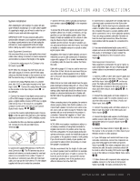
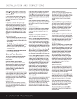
INSTALLATION AND CONNECTIONS device should be made to either the Video 2 Audio Inputs 39 or any of the Optical or Coaxial Digital Input Jacks 33 36 . 8. If the component video inputs are used, connect the Component Video Monitor Outputs b to the component video inputs of your TV, projector or display device. 9. If you have a camcorder, video game or other audio/video device that is connected to the AVR on a temporary rather than permanent basis, connect the audio, video and digital audio outputs of that device to the Front-Panel Inputs &*(Ó. A device connected here is selected as the Video 4 input, and the digital inputs must be assigned to the Video 4 input. (See page 19 for more information on input configuration.) Video Connection Notes: • When the component video jacks are used, the on- screen menus are not visible and you must switch to the standard composite or S-Video input on your TV to view them. • The AVR 325 will accept either standard composite, S-Video or Y/Pr/Pb component video signals. However, it will not convert composite or S signals to component video. • Component and composite video signals may only be viewed in their native formats. System and Power Connections The AVR 325 is designed for flexible use with multiroom systems, external control components and power amplifiers. Main Room Remote Control Extension If the receiver is placed behind a solid or smoked glass cabinet door, the obstruction may prevent the remote sensor from receiving commands. In this event, an optional remote sensor may be used. Connect the output of the remote sensor to the Remote IR Input g jack. If other components are also prevented from receiving remote commands, only one sensor is needed. Simply use this unit's sensor or a remote eye by running a connection from the Remote IR Output h jack to the Remote IR Input jack on Harman Kardon or other compatible equipment. Multiroom IR Link The remote room IR receiver should be connected to the AVR 325 via standard coaxial cable. Plug the IR connection cable into the Multiroom IR Input f jack on the AVR 325's rear panel. If other Harman Kardon compatible source equipment is part of the main room installation, the Remote IR Output h jack on the rear panel should be connected to the IR IN jack on source equipment. This will enable the remote room location to control source equipment functions. NOTE: All remotely controlled components must be linked together in a "daisy chain". Connect the IR OUT jack of one unit to the IR IN of the next to establish this chain. Multiroom Connections The AVR 325 is equipped with multizone capabilities that allow it to send a separate audio source to the remote zone from the one selected for use in the main room. Depending on your system's requirement, three options are available for audio connection: Option 1: Use high-quality, shielded audio interconnect cable from the AVR 325's location to the remote room. In the remote room, connect the interconnect cable to a stereo power amplifier. The amplifier will be connected to the room's speakers. At the AVR 325, plug the audio interconnect cables into the Multiroom Audio Output j jacks on the AVR 325's rear panel. Option 2: Connect the Multiroom Audio Output j jacks on the AVR 325 to the inputs of an optional stereo power amplifier. Run high-quality speaker wire from the amplifier to the speakers in the remote room. Option 3: Taking advantage of the AVR 325's built-in seven-channel amplifier, it is possible to use two of the amplifier channels to power speakers in the remote room. When using this option you will not be able to use the full 7.1-channel capabilities of the AVR 325 in the main listening room, but you will be able to add another listening room without additional external power amplifiers. To use the internal amplifiers to power a remote zone, connect the speakers for the remote room location to the Surround Back/ Multiroom Speaker Outputs ,. Before using the remote room you will need to configure the amplifiers for surround operation by changing a setting in the Advanced Select menu, following the instructions shown on page 32. NOTE: For all options, you may connect an optional IR sensor in the remote room to the AVR 325 via an appropriate cable. Connect the sensor's cable to the Multiroom IR Input f on the AVR 325 and use the Zone II remote to control the room volume. Alternatively, you may install an optional volume control between the output of the amplifiers and the speakers. A-BUS® Installation Connections The AVR 325 is among the very few receivers available today that offer built-in A-BUS Ready® operation. When used with an optional A-BUS keypad or control module, you have all the benefits of remote zone operation without the need for an external power amplifier. To use the AVR 325 with an approved A-BUS product, simply connect the keypad or module that is in the remote room to the AVR 325 using standard Category 5 wiring that is properly rated for the in-wall use specific to the installation. Terminate the wiring at the receiver end to a standard RJ-45 jack in compliance with the instructions furnished with the A-BUS module. No further installation or adjustment is needed, as the A-BUS connector on the AVR 325 routes the signals in and out of the keypad to their proper destination for power, signal source and control. The output fed to the A-BUS jack is determined by the AVR 325's multiroom system, and the menus may be used as is. RS-232 Connections The AVR 325 includes an RS-232 serial port connection that may be used to control the unit via compatible optional, external keypads or control systems. The physical connection to the AVR 325 from the control device is a standard D-9 connection, but to ensure compatible and proper operation, specific software commands and pin wiring schemes are required. Due to the complexity of RS-232 connections, we recommend that they be made only by trained installers familiar with their use. To obtain additional information on the use of the AVR 325 with RS-232 control, please contact Harman Kardon's customer service department or consult our Web site at www.harmankardon.com. AC Power Connections This unit is equipped with two accessory AC outlets. They may be used to power accessory devices, but they should not be used with high-current-draw equipment such as power amplifiers. The total power draw to each outlet may not exceed 100 watts. The Switched AC Accessory Outlet ⁄ will receive power only when the unit is on. This is recommended for devices that have no power switch or a mechanical power switch that may be left in the "ON" position. NOTE: Many audio and video products go into a Standby mode when they are used with switched outlets, and cannot be fully turned on using the outlet alone without a remote control command. The Unswitched AC Accessory Outlet ¤ will receive power as long as the unit is plugged into a powered AC outlet. 16 INSTALLATION AND CONNECTIONS
-
 1
1 -
2
-
3
-
4
-
5
-
6
-
7
-
8
-
9
-
10
-
 11
11 -
 12
12 -
 13
13 -
 14
14 -
 15
15 -
 16
16 -
 17
17 -
 18
18 -
 19
19 -
 20
20 -
 21
21 -
22
-
23
-
24
-
25
-
26
-
27
-
28
-
29
-
30
-
31
-
32
-
33
-
34
-
35
-
36
-
37
-
38
-
39
-
40
-
41
-
42
-
43
-
44
-
45
-
46
-
47
-
48
-
49
-
50
-
51
-
52
-
53
-
54
-
55
-
56
 |
 |