Harman Kardon AVR 325 Owners Manual - Page 9
Surround Back/Multiroom Speaker Outputs - no sound
 |
View all Harman Kardon AVR 325 manuals
Add to My Manuals
Save this manual to your list of manuals |
Page 9 highlights
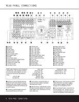
REAR-PANEL CONNECTIONS positive, or "+," terminal that should be connected to the red (+) terminal on the Surround Left speaker with older color-coding, while the gray terminal should be connected to the red (+) terminal on the Surround Right speaker with the older color-coding. Connect the black (-) terminal on the AVR to the matching black negative (-) terminals for each surround speaker. (See page 15 for more information on speaker polarity.) ¶ Front Speaker Outputs: Connect these outputs to the matching + or - terminals on your left and right speakers. When making speaker connections always make certain to maintain correct polarity by connecting the color-coded (white for front left and red for front right) (+) terminals on the AVR 325 to the red (+) terminals on the speakers and the black (-) terminals on the AVR 325 to the black (-) terminals on the speakers. See page 15 for more information on speaker polarity. • Fan Vents: These ventilation holes are the output of the AVR 325's airflow system. To ensure proper operation of the unit and to avoid possible damage to delicate surfaces, make certain that these holes are not blocked and that there is at least three inches of open space between the vent holes and any wooden or fabric surface. ª Center Speaker Outputs: Connect these outputs to the matching + and - terminals on your center channel speaker. In conformance with the new CEA color-code specification, the green terminal is the positive, or "+," terminal that should be connected to the red (+) terminal on speakers with the older colorcoding. Connect the black (-) terminal on the AVR to the black (-) terminal on your speaker. (See page 15 for more information on speaker polarity.) , Surround Back/Multiroom Speaker Outputs: These speaker terminals are normally used to power the surround back left/surround back right speakers in a 7.1 channel system. However, they may also be used to power the speakers in a second zone, which will receive the output selected for a multiroom system. To change the output fed to these terminals from the default of the Surround Back speakers to the Multiroom Output, you must change a setting in the Advanced Menu of the OSD system. See page 32 for more information on configuring this speaker output. In normal surround system use, the brown and black terminals are the surround back left channel positive (+) and negative (-) connections and the tan and black terminals are the surround back right positive (+) and negative (-) terminals. For multiroom use, connect the brown and black SBL terminals to the red and black connections on the left remote zone speaker and connect the tan and black SBR terminals to the red and black terminals on the right remote zone speaker. ⁄ Switched AC Accessory Outlet: These outlets may be used to power any device you wish to have turned on when the AVR 325 is turned on with the System Power Control Button 2. ¤ Unswitched AC Accessory Outlet: This outlet may be used to power any AC device. The power will remain on at this outlet regardless of whether the AVR 325 is on or off. NOTE: The total power consumption of all devices connected to the accessory outlets should not exceed 100 watts. ‹ AC Power Cord Jack: Connect the AC power cord to this jack when the installation is complete. To ensure safe operation, use only the power cord supplied with the unit. If a replacement is required it must be of the same type and capacity. › Video Monitor Outputs: Connect these jacks to the composite or S-Video input of a TV monitor or video projector to view the on-screen menus and the output of any standard video source selected by the receiver's video switcher. fi DVD Video Inputs: Connect the composite or SVideo outputs of a DVD player or other video source to these jacks. fl Video 1 Video Inputs: Connect the composite or S-Video PLAY/OUT jacks of a VCR or other video source to these jacks. ‡ Video 1 Video Outputs: Connect the composite or S-Video REC/IN jacks of a VCR or other video recording device such as a DVD recorder or PVR to these jacks. ° Video 2 Video Inputs: Connect the composite or S-Video PLAY/OUT jacks of a VCR or other video source to these jacks. · Video 2 Video Outputs: Connect the composite or S-Video REC/IN jacks of a VCR or other video recording device such as a DVD recorder or PVR to these jacks. a Video 3 Video Inputs: Connect the composite or S-Video PLAY/OUT jacks of a VCR or other video source to these jacks. b Component Video Monitor Outputs: Connect these outputs to the component video inputs of a video projector or monitor. When a source connected to one of the Component Video Inputs cd is selected, the signal will be sent to these jacks. c DVD Component Video Inputs: Connect the Y/Pr/Pb component video outputs of a DVD player to these jacks. d Video 2 Component Video Inputs: Connect the Y/Pr/Pb component video outputs of an HDTV set-top converter, satellite receiver or other video source device with component video outputs to these jacks. e RS-232 Port: This jack is used to enable the AVR 325 to be controlled by an external computer or programmable remote system that uses RS-232 commands. Due to the complexity of RS-232 connections, we recommend that they be made by a trained and qualified custom installer. See page 16 for more information on the RS-232 control port. f Multiroom IR Input: Connect the output of an IR sensor in a remote room to this jack to operate the AVR 325's multiroom control system. g Remote IR Input: If the AVR 325's front-panel IR sensor is blocked due to cabinet doors or other obstructions, an external IR sensor may be used. Connect the output of the sensor to this jack. h Remote IR Output: This connection permits the IR sensor in the receiver to serve other remote controlled devices. Connect this jack to the "IR IN" jack on Harman Kardon (or other compatible) equipment. i Coaxial Digital Audio Output: Connect this jack to the coaxial digital input of a CD-R/RW, MiniDisc or other digital recorder. j Multiroom Audio Outputs: Connect these jacks to the optional external audio power amplifier and video distribution system that delivers the source selected for multizone distribution. k Optical Digital Audio Output: Connect this jack to the optical digital input connector on a CD-R/RW, MiniDisc or other digital recorder. 31 CD Audio Inputs: Connect these jacks to the analog audio output of a compact disc player or CD changer. 32 DVD Audio Inputs: Connect the left/right analog outputs of a DVD player or other audio source to these jacks. 33 Optical Digital Audio Inputs: Connect the optical digital output from a DVD player, HDTV receiver, the S/P-DIF output of a compatible computer sound card playing MP3 files or streams, LD player or CD player to these jacks. The signal may be a Dolby Digital signal, a DTS signal or a standard PCM digital source. 34 Tape Inputs: Connect these jacks to the PLAY/OUT jacks of an audio recorder. 35 Tape Outputs: Connect these jacks to the RECORD/INPUT jacks of an audio recorder. REAR-PANEL CONNECTIONS 9
-
 1
1 -
2
-
3
-
 4
4 -
 5
5 -
 6
6 -
 7
7 -
 8
8 -
 9
9 -
 10
10 -
 11
11 -
 12
12 -
 13
13 -
 14
14 -
15
-
16
-
17
-
18
-
19
-
20
-
21
-
22
-
23
-
24
-
25
-
26
-
27
-
28
-
29
-
30
-
31
-
32
-
33
-
34
-
35
-
36
-
37
-
38
-
39
-
40
-
41
-
42
-
43
-
44
-
45
-
46
-
47
-
48
-
49
-
50
-
51
-
52
-
53
-
54
-
55
-
56
 |
 |