Harman Kardon AVR80MKII Owners Manual - Page 11
Record/input
 |
View all Harman Kardon AVR80MKII manuals
Add to My Manuals
Save this manual to your list of manuals |
Page 11 highlights
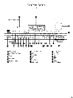
Rear Panel Audio and System Connections 9 C) FM Antenna: Connect an indoor or external FM antenna to these terminals. C) AM Antenna: Connect the AM loop antenna supplied with the receiver to these terminals. If an external AM antenna is used, make connections to the AM and GND terminals in accordance with the instructions supplied with the antenna. Tape 1 Out: Connect these jacks to the RECORD/INPUT jacks of an audio recorder. C) Tape 1 In: Connect these jacks to the PLAY/OUT jacks of an audio recorder. Tape 2 Out: Connect these jacks to the RECORD/INPUT jacks of a second audio recorder. Tape 2 In: Connect these jacks to the PLAY/OUT jacks of a second audio recorder. (i) CD IN: Connect these jacks to the output of a compact disc player or CD changer. O Front R: Connect these terminals to the front right speaker. Front L: Connect these terminals to the front left speaker. 0 Center: Connect these terminals to the center speaker. Surround R: Connect these terminals to the right surround speaker. Surround L: Connect these terminals to the left surround speaker. Subwoofer Pre-Out: Connect this jack to the line level input of a powered subwoofer. If an external subwoofer amplifier is used, connect this jack to the subwoofer amplifier input. O Pre-Outs: If external power amplifiers are used for any channels, remove the jumper pin and connect the jack to the input of the amplifier. C) 6 Channel Direct Input: If an external digital audio decoder is used for 5.1 (Dolby Digital) audio, connect the outputs of that decoder to these terminals. GI Multi Room Interface: For multi- room installations where keypad remotes are in use, connect the keypad interface to this jack. C) Multi IR: Connect the output of an IR sensor in a remote room to this jack to operate the AVR80/ts multiroom control system. Multi-Out: When using the AVR80ii for multi-room audio, connect this jack to the input of the audio amplifier powering the remote room speakers. ID Power Cable: Connect the AC plug to a non-switched AC wall output. Switched AC Outlet: This outlet may be used to power any device that you wish to have on when the unit is turned on. Unswitched AC Outlet: This outlet may be used to power any AC device. The power will remain on at this outlet regardless of whether the AVR80// is on or off. NOTE: The power consumption of the device plugged into each of these outlets should not exceed 120 watts. Remote IR In: If the AVR80/ts front panel IR sensor is blocked due to cabinet doors or other obstructions, an external IR sensor may be used. Connect the output of the sensor to this jack. 0 Remote IR Out: This connection permits the IR sensor in the receiver to serve other remote controlled devices. Connect this jack to the "IR IN" jack on Harman Kardon or other compatible equipment.
-
 1
1 -
2
-
3
-
4
-
5
-
 6
6 -
 7
7 -
 8
8 -
 9
9 -
 10
10 -
 11
11 -
 12
12 -
 13
13 -
 14
14 -
 15
15 -
 16
16 -
17
-
18
-
19
-
20
-
21
-
22
-
23
-
24
-
25
-
26
-
27
-
28
-
29
-
30
-
31
-
32
-
33
-
34
-
35
-
36
-
37
-
38
-
39
 |
 |
