Harman Kardon CD191 Owners Manual - Page 7
Connections
 |
View all Harman Kardon CD191 manuals
Add to My Manuals
Save this manual to your list of manuals |
Page 7 highlights
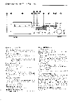
Connections •Always disconnect the AC cords connected to mains outlets before making connections between components. •Use the attached connection cords. Connect the plugs correctly to left and right channel jacks. • Insert plugs fully. Imperfect insertion may cause noise or sound reproduction failure. Connection to the Amplifier or Receiver I I 7,7 @ 0 ==. 0 00 Integrated amplifier •The input jacks of the cassette deck are marked "INPUT". However, they connect to the "tape monitor output" jacks on the receiver or amplifier. •The output jacks of the cassette deck are marked "OUTPUT". However, they connect to the "tape monitor input" jacks on the receiver or amplifier. CD191 AC outlet [=i Connection to Another Tape Deck for Dubbing o Fr= moo. 0 **(: O. -O--\ ,-) Another tape deck UP u Tu v vr 0 0 0 0 •For this application, the input of one tape deck connects to the output of the other. CD191 AC outlet Connecting Headphones and Microphones o o o :Cr CI o•- CD191 Headphones Left microphone Right microphone •Use headphones with impedance more than 82. *When headphones are connected to the HEADPHONES jack, either recording sound can be monitored or playback sound can be listened to without connecting this unit to an amplifier. •Use headphones with the standard connecting plug. •Use low-impedance microphones. (6002 is the standard.) •The recording level can be adjusted by the INPUT LEVEL controls when the INPUT SELECTOR is at the MIC position. •When recording with one microphone, connect it to the left MICROPHONE jack. In this case, a monaural recording is made on both channels. •Use microphones with standard plugs. 6
-
 1
1 -
 2
2 -
 3
3 -
 4
4 -
 5
5 -
 6
6 -
 7
7 -
 8
8 -
 9
9 -
 10
10 -
 11
11
 |
 |
